please forgive what is probably a dumb question... Although I remember doing fourier and laplace transforms at university 34 years ago, I don't remember any of the details. My understanding of signal processing theory is limited...
What would be the result of an LR4 crossover where the high frequency driver was delayed by one full period? A textbook LR4 has a 360 degree phase lag between the LF and HF drivers... so what happens if the HF unit is delayed by 360 degrees?
For example, a 2 kHz LR4 crossover where the HF unit is delayed by 1/2000 = 0.5 ms... my simple minded thinking suggests that this would result in a properly blended step function, but with the advantages of a flat summed response.
Common sense tells me that if this were a workable solution, it would have been done before... so what am I missing?
You'll be in phase exactly at xover frequency, but out of phase around it.
Phase traces will cross at xover freq but not overlay.
So it can be said "in phase, but out of time"
Whereas without the delay, it will be "in phase and in time", and the phase traces will overlay.
I can get good agreement linearizing the phase only of an LR96 at 100Hz with 4096 taps which is about 46ms latency.
Attached is the best I can do with LR8 at 100Hz, 15ms latency and fairly good match to the phase wrap without wrecking the magnitude response.
No free lunch with FIR filters and changing phase 🙂
Your numbers match my experiences.
One cool thing you reminded me of....how much optimization in rePhase can change how well mag matches up.
I think I'll try a little manual sub FIR work again .
Hi xrk. Thanks for sharing info on this Harsch topology! As I also would like some of the "Harsch" sound, I did some experiments lately on my three way open baffle with Fusion amp. Do you think there is a minimum distance between the two crossovers to make this work? I have quite nearby crossovers: 200 Hz and 750 Hz. I get quite severe freq response dips near the crossovers. For LR4 this is not the case. Additional delay compensations helped a bit, but do not solve it...
Fedde
Fedde
Hi Fedde,
Here's what i get out of processor: Harsch 3-way using 200Hz and 750Hz xover points summed back together.
Inputs 1,2,3 on Delay Mixer are High, Mid, Low
Hope it helps

Here's what i get out of processor: Harsch 3-way using 200Hz and 750Hz xover points summed back together.
Inputs 1,2,3 on Delay Mixer are High, Mid, Low
Hope it helps
Thanks Mark, your simulation is greatly appreciated. So it should be possible, although the phase gets a bit higher (up to 90 degree or do) due to the close crossovers. Interestingly, you get actually small peaks around the crossover instead of the large dips (>5 dB) I get...
What tool did you use to make this?
In any case, it is back to the drawing board for me. One of the things I am in doubt is regarding the 1.27 factor for the Bessel filter. I multiplied the fc at 750 Hz LPF with this factor, but wonder about the 200 Hz HPF. I presume I need to divide by this factor for HPF?
Fedde
Hi Fedse,
As Byrtt mentioned, if you artificially increase the XO frequency just a tad, it can reduce the dip/wiggle characteristic of the Harsch XO. But I think your XO points are indeed too close together. Can you push the 700Hz up to a higher region?
That’s slick software Mark100 is using. Yes, what program is that?
Hi guys,
software is q-sys, an open architecture design program, for use on q-sys "core" processors.
I just tried spreading out the xover points a little to see what happens to the bigger phase hump.
Starting with the given xover:
200-750...and its 85 deg hump.
Then:
200-1000..78
150-750 ..78
150-1000..72
So not any major changes i think.
Re the 1.27x factor....my guess is that it comes into play depending on exactly what "type" bessel is being used. There are variations for sure...
The classic txtbook doesn't seem to need anything.
But not my area of expertise...best to check with BTRTT.
Hi Fedse,
As Byrtt mentioned, if you artificially increase the XO frequency just a tad, it can reduce the dip/wiggle characteristic of the Harsch XO. But I think your XO points are indeed too close together. Can you push the 700Hz up to a higher region?
I could try that indeed. I use a PAP 15" Neo woofer, Supravox 8" Bicone and Heil AMT. The drivers are currently quite far from each other, this does probably not help. I like the AMT a lot, so I want to use it as wide range as possible. But 1k crossover could still work. I plan to buy an 18 sounds 6nd430 to replace the Bicone mid. Hopefully I could cross higher (1-2k) with smaller delta in audio quality compared to AMT level...
By the way, despite the dips, I prefer the sound of Harsch XO compared to LR4. Indeed, it is more alive and live sounding. Quite important difference for the music I like (funk, fusion, jazz, world music etc.)
Fedde
Last edited:
Hi Fedde,
Here's what i get out of processor: Harsch 3-way using 200Hz and 750Hz xover points summed back together.
Inputs 1,2,3 on Delay Mixer are High, Mid, Low
Hope it helps
View attachment 868598
On 2nd read, I noticed you have the filters differently as I have. I have LR4 LPF for woofer, B2 for mid HPF, B2 for mid LPF and LR4 for tweeter HPF... I thought it was mentioned like this in the opening post? Is it wrong? 😕
Fedde
@mark100, if you happy incuding the subjective sound performance then i'm happy too, but have to say objective your post 766 looks have quite some ripple if you compare to original HASCH curve paper into post 1 and my fourth animation below for fedde.
@fedde, can't know what exactly is your culprit but as you say maybe narrow bands and also center to center distance plus vertical lobe in XO region will point downwards because filter slope for HARSCH is not in phase as for LR filters.
Using real world narrow bands can give bit trouble if one target a simple per band textbook slope, solution for that is simple to cascade sidebands and stopband into ones acoustic target slope and error goes away as seen in below 4 times animation, first animation is second order LR, second is 4th order LR, third is 8th order LR, and fourth is a hybrid HARSCH at lowest XO region and 4th order LR at highest XO region, because they each animation are unique how much each of the three passbands cooporate to sum each their region each animation have their different looking error when side plus stop bands are omitted.
Use a mouse click inside animations to hinder X/Y ratio distortions:
Attachments


Very cool BYRTT,
May I make two requests...
Pls slow down the animated changes...too fast for this old man to make much sense from !
And would you show static shots of your panels which are optimized Harsch for fedde's xover points.
Pls zoom the vertical scale in so I can compare to the output my processor generated. many Thx!
On 2nd read, I noticed you have the filters differently as I have. I have LR4 LPF for woofer, B2 for mid HPF, B2 for mid LPF and LR4 for tweeter HPF... I thought it was mentioned like this in the opening post? Is it wrong? 😕
Fedde
Fedde, I know very little about this stuff...i'm not an IIR advocate at all.
But i'm super intrigued by any flattish phase IIR designs.
I think YSDR's post #724 along with post #1 by xrk, are the multi-way Harsch formula....or at least that's what i've been going by...
 Wow great stuff Byrtt!
This post is quite deep, I had to read it multiple times to capture its details. It appears that you use even another assembly of filters for Harsch XO. Why do you use Butterworth 4th order for woofer LPF? And no Harsch for mid tweeter crossing?
Fedde
Nice Byrtt!
Thank you - very cool analysis you did. I need to learn VituixCAD. 🙂
Same thought here... 😛
Fedde
Thanks Mark,
Know animations toggles relative fast in 500mS but all information is frozen there during shifts except for curves and they curves will come fast back to the eye or make a print screen 🙂 that said i slow them down next time its just i can't edit that post anymore.
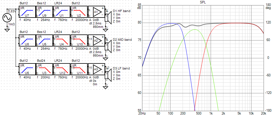
Here are static graphs for numbers and ripple in that fedde theoretical model, have added power amps buffers so as you can see used numbers for delay time or in distance set for MID/HF sections, if your software is not happy that times 1,27 thing for bessel filter then try use 2nd order LR plus one PEQ Q0,58/+1,3dB because then it works use exactly same frequency as for the low pass 4th order BW slope..
Use a mouse click inside animations to hinder X/Y ratio distortions and improve resolution:
Know animations toggles relative fast in 500mS but all information is frozen there during shifts except for curves and they curves will come fast back to the eye or make a print screen 🙂 that said i slow them down next time its just i can't edit that post anymore.
Here are static graphs for numbers and ripple in that fedde theoretical model, have added power amps buffers so as you can see used numbers for delay time or in distance set for MID/HF sections, if your software is not happy that times 1,27 thing for bessel filter then try use 2nd order LR plus one PEQ Q0,58/+1,3dB because then it works use exactly same frequency as for the low pass 4th order BW slope..
Use a mouse click inside animations to hinder X/Y ratio distortions and improve resolution:
Attachments
Last edited:
Thx BYRTT,
What's the phase of that setup?
It looks to have maybe about 0.4dB less magnitude ripple than a standard set of BW4 lowpasses, with BT2 highpasses, and cumulative 1/2 period delays.
But it also looks much more complicated ????
If phase is better though, complication be good 🙂
What's the phase of that setup?
It looks to have maybe about 0.4dB less magnitude ripple than a standard set of BW4 lowpasses, with BT2 highpasses, and cumulative 1/2 period delays.
But it also looks much more complicated ????
If phase is better though, complication be good 🙂
On 2nd read, I noticed you have the filters differently as I have. I have LR4 LPF for woofer, B2 for mid HPF, B2 for mid LPF and LR4 for tweeter HPF... I thought it was mentioned like this in the opening post? Is it wrong? 😕
Fedde
My understanding is use BW4 for every lowpass, bessel2 for every high pass.
Each higher section needs to be delayed by 1/2 period of its fc, and delays need to add cummutavly.
I keep going by 2-way instructions in post #1 and multi-way in #724.
If these are in err, someone will let us know I guess...
- Home
- Loudspeakers
- Multi-Way
- S. Harsch XO