Hi there,
as I am now finding some time to continue work on my version of Allen Wrights PP1C (EL34-PP), I will post the progress and the (surely coming) open questions in this thread instead of starting many new ones.
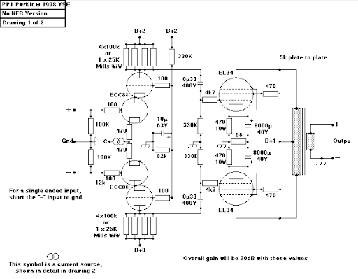
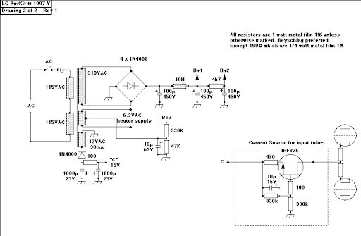
The original schematic by A. Wright:
A short list of older posts directly concerning this project:
http://www.diyaudio.com/forums/tubes-valves/62937-suggestions-tube-amplifier.html
http://www.diyaudio.com/forums/tubes-valves/65736-more-questions-about-wrights-pp1c.html
http://www.diyaudio.com/forums/tubes-valves/10461-all-tube-ccs.html
http://www.diyaudio.com/forums/tubes-valves/65984-how-much-ripple-b-allowed.html
http://www.diyaudio.com/forums/tubes-valves/179148-power-supply-pp1c-sanity-check.html
http://www.diyaudio.com/forums/tubes-valves/180127-tube-ccs-below-cathodes-startup-issues.html
The current planning/situation:
* GZ34 power supply reproduces or exceeds specs of original supply (PSUD, not built yet)
* startup issue will be solved by a defined power-up sequence delaying the -HV rail
* first parts arrived 🙂
Greetings,
Andreas
as I am now finding some time to continue work on my version of Allen Wrights PP1C (EL34-PP), I will post the progress and the (surely coming) open questions in this thread instead of starting many new ones.
The original schematic by A. Wright:
A short list of older posts directly concerning this project:
http://www.diyaudio.com/forums/tubes-valves/62937-suggestions-tube-amplifier.html
http://www.diyaudio.com/forums/tubes-valves/65736-more-questions-about-wrights-pp1c.html
http://www.diyaudio.com/forums/tubes-valves/10461-all-tube-ccs.html
http://www.diyaudio.com/forums/tubes-valves/65984-how-much-ripple-b-allowed.html
http://www.diyaudio.com/forums/tubes-valves/179148-power-supply-pp1c-sanity-check.html
http://www.diyaudio.com/forums/tubes-valves/180127-tube-ccs-below-cathodes-startup-issues.html
The current planning/situation:
* GZ34 power supply reproduces or exceeds specs of original supply (PSUD, not built yet)
* startup issue will be solved by a defined power-up sequence delaying the -HV rail
* first parts arrived 🙂
Greetings,
Andreas
Last edited:
Cathode resistor choice - a matter of taste?
Hi there,
I was planning to use these resistors below the EL34 cathodes: Ohmite 470R, 10W, 1%, wirewound
Via a german electronic surplus store, I also got these extremely cheap: Vishay Dale 470R, 10W, 1%, wirewound
I guess the Dales can dissipate the 10W only when attached to a heatsink oder chassis, while the first ones might be mounted in free air. What do you think, is it a matter of taste or are the reasons to prefer one of the two?
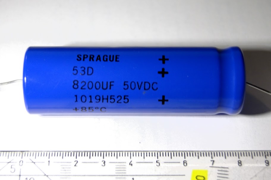
Cathode bypass capacitors will be these: Sprague 8000µF, 50V, axial
Greetings,
Andreas
Hi there,
I was planning to use these resistors below the EL34 cathodes: Ohmite 470R, 10W, 1%, wirewound
Via a german electronic surplus store, I also got these extremely cheap: Vishay Dale 470R, 10W, 1%, wirewound
I guess the Dales can dissipate the 10W only when attached to a heatsink oder chassis, while the first ones might be mounted in free air. What do you think, is it a matter of taste or are the reasons to prefer one of the two?
Cathode bypass capacitors will be these: Sprague 8000µF, 50V, axial
Greetings,
Andreas
Have you looked at the Sprague 678D series, I think there is an axial version (maybe the one you have) that has a very low impedance as well.
As far as the resistor, look them up and check for the lowest inductance.
As far as the resistor, look them up and check for the lowest inductance.
Hello Rundmaus,
This is really a great amp!
I suggest that you use a current source instead of the big cathode resistors and the caps.
In the later version, the PP1CS, Allen use a single FET, 9 Volt battery and 3 resistors. You might get a copy of the schematic if you send him an email?
But hey, it's just a very simple ccs. 🙂
Be sure to make the PSU choke loaded and the choke should be no less than 8H. You might consider using polypropylene motor run caps in the PSU? 😉
Prepare the amp for a (shunt) voltage regulator for the driver stage. 😉
Choose the OPT and transformer so you can upgrade the amp for 300Bs and 6H30... 😉
Happy building! 😀
Hi there,
just finished a first layout idea for the amp. Chassis shown is sized 50cm by 40cm. All components drawn to scale (except connectors and HV caps, only approx.).
Image is a top view, tubes, controls and connectors will be on the upper side, all iron below.
As nothing interesting is expected to happen at the rectifier sockets, they are covered by a subchassis carrying the chokes. Distance will be provided to ensure enough air flow to the rectifiers.
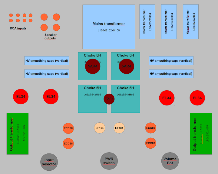
Any comments? 🙂
Greetings,
Andreas
just finished a first layout idea for the amp. Chassis shown is sized 50cm by 40cm. All components drawn to scale (except connectors and HV caps, only approx.).
Image is a top view, tubes, controls and connectors will be on the upper side, all iron below.
As nothing interesting is expected to happen at the rectifier sockets, they are covered by a subchassis carrying the chokes. Distance will be provided to ensure enough air flow to the rectifiers.
Any comments? 🙂
Greetings,
Andreas
Last edited:
I was planning to use these resistors below the EL34 cathodes: Ohmite 470R, 10W, 1%, wirewound
Via a german electronic surplus store, I also got these extremely cheap: Vishay Dale 470R, 10W, 1%, wirewound
I guess the Dales can dissipate the 10W only when attached to a heatsink oder chassis, while the first ones might be mounted in free air. What do you think, is it a matter of taste or are the reasons to prefer one of the two?
The Ohmite resistors will allow for 10 W dissipation at an ambient temperature of 25 deg C. At this dissipation, you can expect their temperature to approach 250~300 deg C (yes C!).
The Vishay-Dale RH-10 series can dissipate up to 60 % of its rated power at 25 C ambient without a heat sink. Their 10 W rating is based on them being chassis mounted. See the RH-10 datasheet for more details.
With power resistors in general, I recommend a significant design margin. I wouldn't allow for more than 1/4~1/3 of the rated power to be dissipated in a power resistor. Even under those conditions, the resistors will be over 100 deg C at 25 C ambient!
As long as you can get good air flow around the Ohmite resistor, that's probably what I would go with. I don't like using the chassis for a heat sink on products that the user can touch. But if you're fine with heating up the chassis, it's really up to you which resistor you choose to use. There's no significant advantage one way or the other.
~Tom
Interesting amp, I might build one someday 😛
I'm just wondering, why a huge 8000 uF 😱 cathode cap??
I'm just wondering, why a huge 8000 uF 😱 cathode cap??
The big cathode bypass cap is a recomendation from AW going way back. I´m not sure why but I think it has to do with minimal LF phase shift, and an "on ear" improvement reported by AW.
Hi there,
Any comments? 🙂
Greetings,
Andreas
You´ve got quite long runs of cable back and forth to the input/ output jacks. A friend of mine is building an amp in this tread: http://www.hifisentralen.no/forum/index.php/topic,47654.0.htmlIt´s very well planned. Check it out!
I like AWs designs too and have for long been planning to build an amp like the one you are doing.
Surplus surplus, surprise
Hi there,
the *really* cheap heater transformers from a german electronics surplus have arrived... 😱
They smell awfully 😕, deliver 6V/2A per winding at 220V mains, so should be 6,3V at 230V mains. As they look quite rotten, they will probably only serve for testing purposes. They sold for 3,50 Euro per piece, which is ok for a test setup...
For the final amplifier a custom-wound heater transformer will be ordered - unless some forum member knows a source for a transformer with 6.3V/4A, 6.3V/4A, 6.3V/3A secondaries.
Any more comments to the chassis above? The long signal path is gone, I will move the input selector directly to the sockets and fit a mechanical solution to operate it from the front, same for the power switch, which will then be located near the mains transformer.
Greetings,
Andreas
Status update
Hi there,
the project has *not* been abandoned - I just do not have much time besides everyday work...
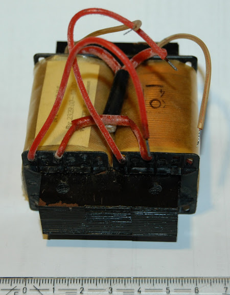
Right now, the custom-wound mains transformer has arrived:

Looks quite good - still have to check if all values are as stated.
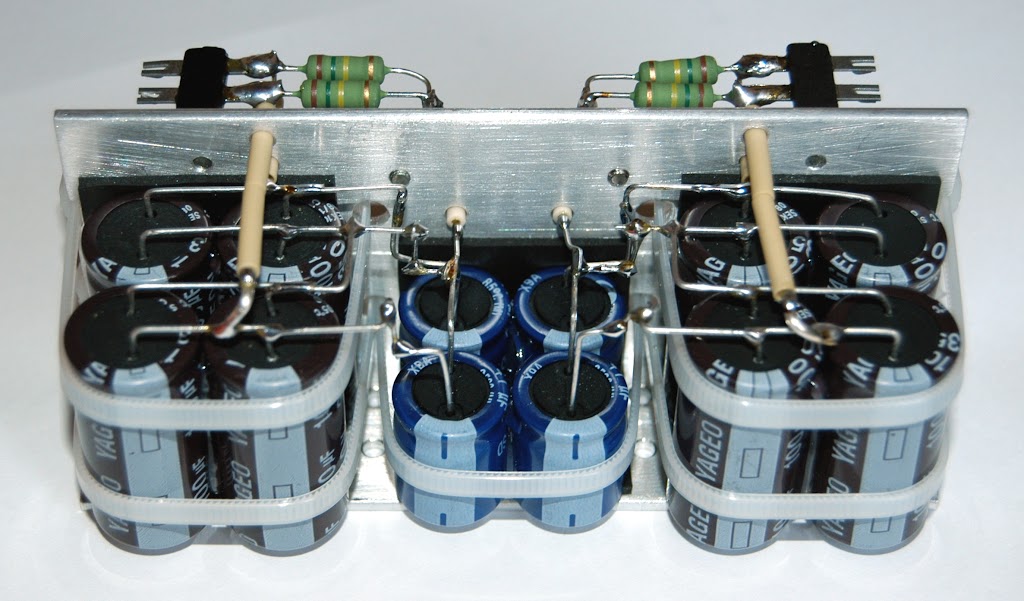
Also, I found some time to build one of the B+ filter assemblies for the test setup, consisting of 2x 120µF with bleeder resistors. The caps used are 385V rated - I connected two in series because the off-load voltage of the PSU is about 650V.
I plan to break the circuit apart into large sub-assemblies to make the building of the final amplifier a little more easy. More filtering for the phase-splitter and the negative rail will be made the same way.
Greetings,
Andreas
Hi there,
the project has *not* been abandoned - I just do not have much time besides everyday work...
Right now, the custom-wound mains transformer has arrived:
Looks quite good - still have to check if all values are as stated.
Also, I found some time to build one of the B+ filter assemblies for the test setup, consisting of 2x 120µF with bleeder resistors. The caps used are 385V rated - I connected two in series because the off-load voltage of the PSU is about 650V.
I plan to break the circuit apart into large sub-assemblies to make the building of the final amplifier a little more easy. More filtering for the phase-splitter and the negative rail will be made the same way.
Greetings,
Andreas
Still there *gg*
Hi there,
there wasn't much time for DIY stuff in 2011, working on my PhD kept me from grabbing the soldering iron, financial issues kept me from buying the Lundahl iron for the test setup...
Found some time now to continue with the amp, the negative rail for the pentode CCS below the phase splitter cathodes is up and working:
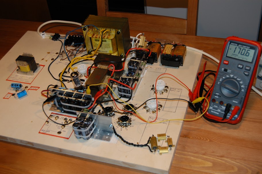
It is a cap input supply being fed from a EZ81 rectifier tube, filtering as follows:

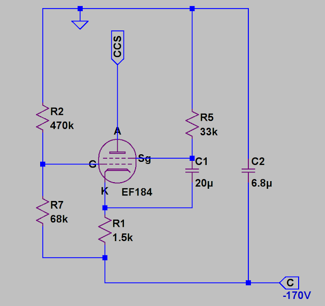
Afterwards, the EF184 constant current sink was build, after weeks of fiddling around with LTSpice to find suitable parameters. I used to think that simulating stuff saves time, but it seems to be the other way round... 😱
Schematic:
And yes, it works!
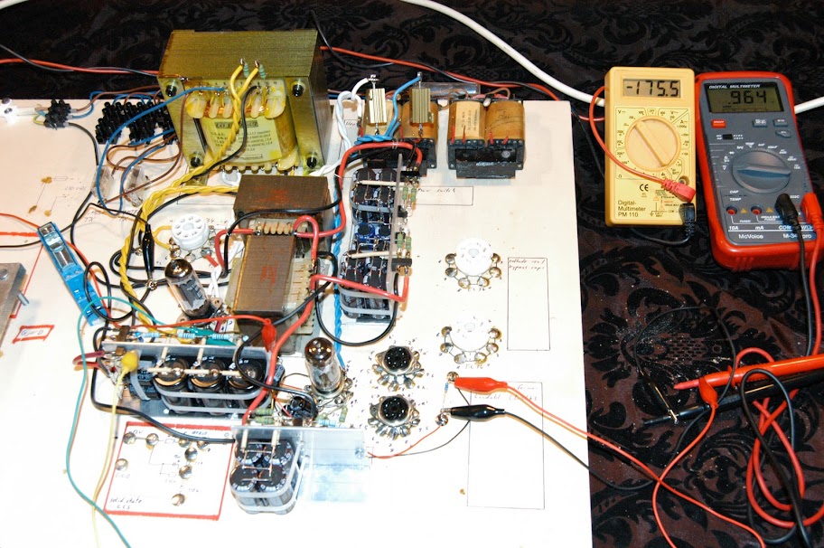
The small, yellow DMM shows the negative rail voltage, the larger one measures the voltage across a 100 ohms resistor, giving a readout for the programmed current (9.6mA). The CCS is built around the EF184 seen below the middle of the image, the second tube visible to the left side is the EZ81 of the negative rail.
The GZ34 rectifier has been pulled because I don't need the positive rail for the testing, seems safer without having 400V present everywhere... And saves tube life by avoiding all the on/off switching.
Best regards,
Andreas
PS: Edith says that none of my earlier posts mentioned that the positive rail is up and working fine, apart from a slow up/down drift of the DC voltage which is probably due to mains variations.
Hi there,
there wasn't much time for DIY stuff in 2011, working on my PhD kept me from grabbing the soldering iron, financial issues kept me from buying the Lundahl iron for the test setup...
Found some time now to continue with the amp, the negative rail for the pentode CCS below the phase splitter cathodes is up and working:
It is a cap input supply being fed from a EZ81 rectifier tube, filtering as follows:
Afterwards, the EF184 constant current sink was build, after weeks of fiddling around with LTSpice to find suitable parameters. I used to think that simulating stuff saves time, but it seems to be the other way round... 😱
Schematic:
And yes, it works!
The small, yellow DMM shows the negative rail voltage, the larger one measures the voltage across a 100 ohms resistor, giving a readout for the programmed current (9.6mA). The CCS is built around the EF184 seen below the middle of the image, the second tube visible to the left side is the EZ81 of the negative rail.
The GZ34 rectifier has been pulled because I don't need the positive rail for the testing, seems safer without having 400V present everywhere... And saves tube life by avoiding all the on/off switching.
Best regards,
Andreas
PS: Edith says that none of my earlier posts mentioned that the positive rail is up and working fine, apart from a slow up/down drift of the DC voltage which is probably due to mains variations.
Last edited:
AW was a firm proponent of using good chokes in the power supply and wasn't particularly bothered about using tube rectifiers. I see you have gone the opposite way.
AW was a firm proponent of using good chokes in the power supply and wasn't particularly bothered about using tube rectifiers. I see you have gone the opposite way.
Hi ihear21khz,
only the negative rail for the current sink is chokeless, due to the low current demands here, it was simpler and smaller with caps and resistors than with chokes. The positive supply for the amp is choke-input 😀
That thing about tube rectifiers is (luckily) no 'religious' question for me. I am aware that the power supplies as well as the current sink would have been much easier with the help of solid state devices. And I do not expect significant performance improvements from keeping solid state stuff out of this project.
It was just an interesting idea for me to build that amp without any semiconductor, although this means that some things are more difficult/bulky/expensive then.
I will report back when the amp is working - which basically means when I have some money to get an output transformer... 🙄
Regards,
Andreas
Hi ihear21khz,
I will report back when the amp is working - which basically means when I have some money to get an output transformer... 🙄
Regards,
Andreas
You won't regret building this. I have the PP1s and they are great sounding amps. If not for my power hungry speakers, I'd use one or the even better sounding PP2.
Following your project too, and also have a plan to build the pp-2 some day. OPT, PT and chokes are inhouse.
You won't regret building this. I have the PP1s and they are great sounding amps. If not for my power hungry speakers, I'd use one or the even better sounding PP2.
Yes, I am really looking forward to listening to that one for the first time - though my test-setup provides only one channel... As stated above, the project is mainly delayed by financial issues - I used to think that the custom-wound power transformer was expensive, but the OPT costs even more, not to mention a set of tubes for one channel....
Regards,
Andreas
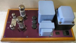
my version of the PP1C
In the year 2000, after finding the original Allen Wright schematic on the Internet (see the schematic at the start of this thread), I made these two monoblock amplifiers.
Vacuum tubes: 2 x Cca (Siemens) and 2 x EL34 (Telefunken).
Transformers were rescued from old amplifiers.
I followed the original schematic.
I used good quality commercial components, no fancy expensive stuff.
I am very satisfied with the result and sound quality of this design, now driving a pair of Klipsch Heresy III speakers.
Best regards, 968driver.
Attachments
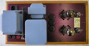
Transformers were rescued from old amplifiers.
Do I correctly recognize the 1L452 Output transformers as used by carad/artec in their EL34 PP amps?
The power transformer is from an Artec EL34 PP stereo amplifier (the one with the horizontal VU meters, they used two of these in the stereo amp, so this is good for two monoblock amps).
The output transformers however, are French Millerioux PP transformers.
The choke on top of the chassis is from an old Hewlett Packard instrument.
All were cleaned and spray painted in Provence blue, inspired by a holiday in the beautiful Provence region of France.
The donnor amplifiers were beyond rescue.
Best regards, 968driver.
- Home
- Amplifiers
- Tubes / Valves
- Rundmaus at work - PP1C without sand