This was only in the context of a line stage followed by a dc power amp. The speakers may see more than 10v dc before the 0.5v threshold is reached.
The idea of this board is not to protect loudspeakers from DC. There is another XRK board available for this purpose.
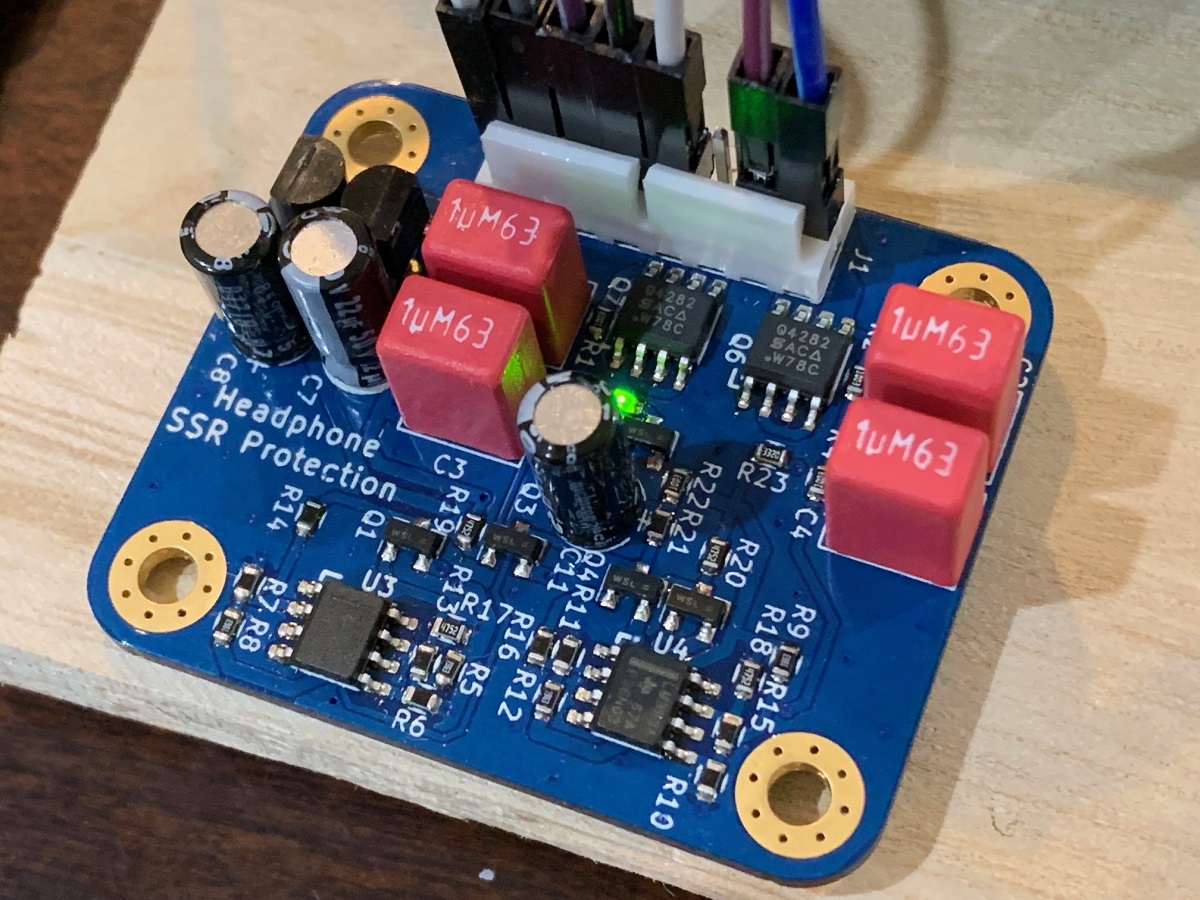
The primary purpose of this board is to protect headphones from DC.
Due to seeming lack of interest in a RTR SSR HPA protection circuit, I will offer these as bare PCBs for DIYers willing to do 0810 SMT soldering. However, Mbrennwa couldn’t wait so I sold him my one ready-made unit. I need to order these PCBs though and good timing with the recently released SFP soft start circuit boards which also needs to be made.
@Mbrennwa,
Have fun with it and let us know how you like it!
@Mbrennwa,
Have fun with it and let us know how you like it!
Heya X,
I'd be keen on a few of these boards 😀. Is it possible to adjust the offset sensitivity?
I'd be keen on a few of these boards 😀. Is it possible to adjust the offset sensitivity?
@DontHertzMe,
If you mean can the voltage trip level be adjusted, the answer is yes. It is adjusted with a pair of resistors for each comparator so it would mean changing some resistor values. I'll need to refresh my memory to determine which ones and how to set those thresholds. You can PM me to tell me what levels you want or wait for me to respond again to this thread.
If you mean can the voltage trip level be adjusted, the answer is yes. It is adjusted with a pair of resistors for each comparator so it would mean changing some resistor values. I'll need to refresh my memory to determine which ones and how to set those thresholds. You can PM me to tell me what levels you want or wait for me to respond again to this thread.
@DontHertzMe,
If you mean can the voltage trip level be adjusted, the answer is yes. It is adjusted with a pair of resistors for each comparator so it would mean changing some resistor values. I'll need to refresh my memory to determine which ones and how to set those thresholds. You can PM me to tell me what levels you want or wait for me to respond again to this thread.
I typically shoot for offset less than 20mV, so ideally I'd like to be able to set the protection circuit to around that value. I'm sure others have their own preferred threshold.
My honest opinion is that roughly 20 millivolts is too low. Lets look at the schematic accompanying post #1. I'll look at the left in signal, positive threshold. It is set by the ratio of R5 and R6 and the hysteresis by R13 and for the positive trip point R17. The voltage at the comparator - input will be 5V*(R6/(R5 + R6) plus the influence of R13 + R17. Those numbers turn out to be 496 millivolts plus about 80 millivolts for an upper trip point of about 0.58 volts. When the comparator changes state one side of R13 is pulled to ground so the lower trip point will be the 496 millivolts minus roughly 6 millivolts from R13 pulling it down.
You can go through similar analysis for the negative half of the of the setpoint with R7, R8 and R14 hysteresis. And for the right channel the setpoints are a function of R9, R10, R15 and R11, R12, R16.
If you want to reduce the nominal setpoints then change the 21.5K resistors to something lower.
You can go through similar analysis for the negative half of the of the setpoint with R7, R8 and R14 hysteresis. And for the right channel the setpoints are a function of R9, R10, R15 and R11, R12, R16.
If you want to reduce the nominal setpoints then change the 21.5K resistors to something lower.
Thank you kindly for the information 😀. That's really useful.
In my experience anything greater than 50mV means something is wrong with the amp. So based on your helpful equation that means changing R6 and R7 to 2.2k would yield a trip level of ~55mV.
In my experience anything greater than 50mV means something is wrong with the amp. So based on your helpful equation that means changing R6 and R7 to 2.2k would yield a trip level of ~55mV.
I agree with your notion that something greater than 50 mV means something is wrong. The protection circuit's purpose is to protect your headphones if that happens.
The idea of this board is not to protect loudspeakers from DC. There is another XRK board available for this purpose.
The primary purpose of this board is to protect headphones from DC.
How is your SSR DC protection board working out for you?
Sorry for my slow response. My headphone amp is making progress, but it's slow. I was busy with lots of other stuff... It's amazing what the combination of Corona limitations + holiday season does! Rebuilding the garden house is just one of the things that keep me busy...
I am offering these SSRs in my shop now as bare PCBs since there as not enough interest to make them fully assembled for a GB.
X,
TRS headphone plugs create momentary short circuits when being inserted or removed (hotplugging of different headphones for example).
Can these headphone protect pcb's help with preventing such short circuits and possibly damaging sensitive transistors such as output MOSFETs in certain headphone amp designs?
Thanks,
Anand.
These SSR DC protect circuits will not prevent a very brief impulse (or pop) from hot-plugging TRS/XLR jacks. They do have a turn on delay of a bout 2 seconds. In general, it is not advised to hot-plug audio input connectors to a live amp connected to a headphone or speaker. Most of the time, my lower power headphone amps have not caused a problem. But I would be cautious of amps capable of more than 100mW output, especually for sensitive IEM's.
A hot-plugging induced pop on a 1200w amp like IcePower 1200AS2 can drive the voice coil of a speaker out onto the floor. 🙂
A hot-plugging induced pop on a 1200w amp like IcePower 1200AS2 can drive the voice coil of a speaker out onto the floor. 🙂
I understand the dangers of hot plugging on the input side of any amplifier whether it be a headphone amp or speaker amp (although Tom C’s amp designs DO allow you to do that).
My question is with regards to the OUTPUT side and how hotplugging a headphone (particularly on the TRS output) can affect the output stage of said amplifier. Particularly the output transistors should they be MOSFETS.
But it sounds like that’s a no go too! :-(
Best,
Anand.
My question is with regards to the OUTPUT side and how hotplugging a headphone (particularly on the TRS output) can affect the output stage of said amplifier. Particularly the output transistors should they be MOSFETS.
But it sounds like that’s a no go too! :-(
Best,
Anand.
Last edited:
On the output stage of a MOSFET headphone amp, I don’t see any issues if the amp is properly designed. If you are using this SSR DC protect circuit, it will actually help to protect the amp in the case of momentary short circuit as that causes a substantial DC offset. The relay will open, preventing damage. If the short is so brief as to not cause a substantial offset as detected by the comparator, then nothing happens (and no harm done) as the offset from the short is not really that big of an issue. I have never had an amp BJT or MOSFET fail from hot plugging a headphone jack into or out of the amp.
Hi X, Jhofland, others...
I am populating a Mouser order for this board and I am wondering with the worldwide semiconductor shortage if there are some substitutes.
Specifically Q1-Q5 which are specified as BSS 138 and also U5, U6 which are specified as TLP3906_Opto.
Q1-Q5 are SOT23 Mosfets:
BSS138L onsemi / Fairchild | Mouser
U5 and U6 are Photodiode Optocouplers:
TLP3906(E Toshiba | Mouser
I have also changed R6, R7, R10 and R11 to 2.2k instead of 21.5k as I would like the trip point for the circuit to engage at ~ 50mV instead of ~ 580mV.
I've already checked Digikey and Octopart so don't bother. The question really is, are there any workable substitutes for the above semiconductors?
Thanks,
Anand.
- Home
- Group Buys
- RTR SSR Headphone Amplifier DC Protection Modules GB