Those parts are common as grass 😉
Try Digikey
www.digikey.com
or Mouser
www.mouser.com
both sell them in piecewise quantities.
Have fun, Hannes
Try Digikey
www.digikey.com
or Mouser
www.mouser.com
both sell them in piecewise quantities.
Have fun, Hannes
OK, I found a good source for MJ21193/4 here in Canada.
Now I just need to know what type of matching will be required?
Is hfe alone enough?
The bigger question is how many devices in excess of my requirements will I need to get good matches?
25% more, 50%, double?
Now I just need to know what type of matching will be required?
Is hfe alone enough?
The bigger question is how many devices in excess of my requirements will I need to get good matches?
25% more, 50%, double?
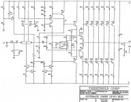
h_a said:@georgehifi: thanks for the schematic!
Fan of quick mick, eh? 😀
Have fun, Hannes
If you like that, your guna luv the rest
Attachments
Hi ungie,
If you buy enough parts at one time, an hFE match is enough. The E-B voltages from the same batch will be enough for sure.
When I need to match outputs, I have to buy more depending on how many need to be matched. It's easier to get a matching pair than it is to get 9 matched (like the Model 5 I am working on right now). This output configuration does need the output transistors to be matched reasonably closely. When a manufacturer buys his parts, he will get devices from one run normally. They are generally close out of the box in this situation. If you need to know how close for sure, then measure the outputs from the undamaged amplifier to see how close they are. That will be your only true answer.
Listen to djk, he's given you excellent information so far.
Hi The golden mean,
NTE parts seem to work in TVs though (I'm told). Mind you, those same people fix stereos with them too. 🙄
-Chris
If you buy enough parts at one time, an hFE match is enough. The E-B voltages from the same batch will be enough for sure.
When I need to match outputs, I have to buy more depending on how many need to be matched. It's easier to get a matching pair than it is to get 9 matched (like the Model 5 I am working on right now). This output configuration does need the output transistors to be matched reasonably closely. When a manufacturer buys his parts, he will get devices from one run normally. They are generally close out of the box in this situation. If you need to know how close for sure, then measure the outputs from the undamaged amplifier to see how close they are. That will be your only true answer.
Listen to djk, he's given you excellent information so far.
Hi The golden mean,
Only a service person who doesn't know any better! That stuff is highly variable and totally unsuited for audio repairs. I have first hand knowledge of this (I refuse to use that stuff). If I see these in a repair, they are on the replacement list. Non-negotiable or I won't touch the unit. Even their replacement guide is suspect. I've seen people cross reference in and out as well!Well, it´s always possible to measure transistors and not everyone is that negative to NTE.
NTE parts seem to work in TVs though (I'm told). Mind you, those same people fix stereos with them too. 🙄
-Chris
ungie said:OK, I found a good source for MJ21193/4 here in Canada.
Now I just need to know what type of matching will be required?
Is hfe alone enough?
The bigger question is how many devices in excess of my requirements will I need to get good matches?
25% more, 50%, double?
You don't need to match devices, and the 1 ohm Emitter resistors are more
than adequate to cover the current sharing.
😎
Hi Nelson,
I guess if the standing bias current is high enough, that has got to be true. I have no idea what the bias is on these Rowland amplifiers, or even if the output stage is inside a feedback loop or not. In your Threshold (Stassis) designs, that is certainly true. At lower currents, the emitter resistors do become less effective.
However, I am positive that the devices must be the same type number. The amp would probably work with a mix of part numbers, but not well. I haven't tried this.
-Chris
anatech said:I have no idea what the bias is on these Rowland amplifiers, or even if the output stage is inside a feedback loop or not. -Chris
Thanks Chris and Nelson!
djk suggested in an earlier post that there is no global fb on these designs and hence matching is required.
I have no idea if that's true or not but my quick tracing of the driver/ouput stage suggests that this might be correct.
The PNPs are usually very close, close enough to not bother with testing.
The NPNs vary at low currents, as Nelson pointed out a high value emitter resistor may be good enough to force a match.
I always bought in flats of 100 pcs and marked each device. I used enough NPNs in PA amps that I could use 100% of the devices (over time).
The NPNs vary at low currents, as Nelson pointed out a high value emitter resistor may be good enough to force a match.
I always bought in flats of 100 pcs and marked each device. I used enough NPNs in PA amps that I could use 100% of the devices (over time).
I would pretty much Take nelsons work as gospel! 1 ohm emitter resistors is pretty big. I normally see ..33 to .47 an average some some being .1
ONE ohm is pretty rare and i would think pretty loose tolerances will even out with that big of an Emitter resistor.
I would pull all the remaining transistors from that channel and read the Articles on PASSDIY about Mosfet matching. the principal is the same and the same test rig will work. You can then get an idea of how close of a match they are from the factory.
The test rig basically is a set up to turn on one device so that it is drawing a certain current through a resistor. you then shut the power off, insert another device and note the difference in current being drawn. pretty simple.
So for example, lets just say your measuring at 50ma. the number is arbitrary for this point in discussion. you set up the rig to read 50ma. then insert the next device and lest say it measure 54ma, and the next 46ma and you go through the lot and figure out what the spread of numbers is. then....IF you can find real D555/B600 devices, you can then test the lot of the new devices on the same rig, with the same settings and they must be exact so do it all at once...You can then find new devices that fall within the range of the spread of the existing devices.
You should set up the rig to match at the bias current. so figure out what that is per device and set the rig up to match at that number.
OR, buy all new MJ devices. match them the best you can and pop em in there.
Even though thus lord god king of amplifiers has handed down his words on this. thank you thank you thank you all hail NP. ...as a perfectionist i would still test the lot of new devices just to weed out any that are way out of range. I just wouldn't be quite as picky as i normally would.
Zc
Hi ungie,
I was speaking with Jeff Rowland recently. The output stage will probably run at 55 ~ 80 mA for each output. At least that's where the model 5 is sitting. He probably runs his other amps around the same bias current. Thus, the bias current is high enough to keep reasonably matched outputs running close to each other. The replacements (if required) would be the On Semi MJ21195 and 21196. I'd buy some extra and cull the ones that measure too high or low in hFE. Mr. Rowland does have some of those Japanese devices left for his service use.
There is no feedback around the output stage. Therefore, the closer the outputs match, the lower THD there will be - within reason. There is no need to match them very tightly.
The hFE matching will determine how nicely the output stage behaves in the zero crossing region where the lower bias currents allows more of an effect. At higher signal (current) levels, the 1 ohm resistors will swamp out hFE variations and force current sharing.
BTW, on a stereo amp, you can simply ship one output heat sink assembly to him for service. He does not require the entire amplifier. I can't see how your mono amp is put together, but there may be a sub assembly you could ship rather than the entire amplifier.
Hi Zero Cool,
-Chris
I was speaking with Jeff Rowland recently. The output stage will probably run at 55 ~ 80 mA for each output. At least that's where the model 5 is sitting. He probably runs his other amps around the same bias current. Thus, the bias current is high enough to keep reasonably matched outputs running close to each other. The replacements (if required) would be the On Semi MJ21195 and 21196. I'd buy some extra and cull the ones that measure too high or low in hFE. Mr. Rowland does have some of those Japanese devices left for his service use.
There is no feedback around the output stage. Therefore, the closer the outputs match, the lower THD there will be - within reason. There is no need to match them very tightly.
The hFE matching will determine how nicely the output stage behaves in the zero crossing region where the lower bias currents allows more of an effect. At higher signal (current) levels, the 1 ohm resistors will swamp out hFE variations and force current sharing.
BTW, on a stereo amp, you can simply ship one output heat sink assembly to him for service. He does not require the entire amplifier. I can't see how your mono amp is put together, but there may be a sub assembly you could ship rather than the entire amplifier.
Hi Zero Cool,
There are a few other amps using 1 ohm emitters. Stasis designs for sure, which includes the Nakamichi PA-5 and PA-7 (same for type IIs).ONE ohm is pretty rare and i would think pretty loose tolerances will even out with that big of an Emitter resistor.
-Chris
anatech said:Hi ungie,
I was speaking with Jeff Rowland recently. The output stage will probably run at 55 ~ 80 mA for each output. At least that's where the model 5 is sitting. He probably runs his other amps around the same bias current. Thus, the bias current is high enough to keep reasonably matched outputs running close to each other. The replacements (if required) would be the On Semi MJ21195 and 21196. I'd buy some extra and cull the ones that measure too high or low in hFE. Mr. Rowland does have some of those Japanese devices left for his service use.
-Chris
Thanks Chris!
I'll get around to measuring the output device current on the functioning monoblock sometime today.
I'm wondering why you would pick the MJ21195/96 over the MJ21193/94?
They seem to have very close specs with the MJ21193/94 having flatter current characteristics.
The 93/94 devices also seem to be easier (and cheaper) to find in small lots.
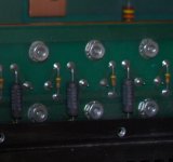
As for sending back the output stage/heatsink for repair...I don't think this is necessary as it looks like the repair will be straightforward. The other comment I can make on these early amps is, how do I put this politely, that little thought was put into disassembly for servicing.

Just getting the output devices unbolted for testing was a chore.
The support rail for the top cover would not allow a nut driver to be used on the TO3 nut closest to this rail. Plus there is very little clearance to each emitter resistor to get a crescent wrench in there!
See the photo below:
Attachments
Hi ungie,
On Semi finally came a long way when they came out with these newer transistors. Something we've needed in North America for a long, long time. Now all we need are great signal transistors like some of the Japanese parts.
-Chris
I normally spec that series and I'm getting lazy in my old age. That and I just finished working on an amp that needed the higher ratings. The 93/94 transistors are every bit as good as the ones I mentioned.I'm wondering why you would pick the MJ21195/96 over the MJ21193/94?
On Semi finally came a long way when they came out with these newer transistors. Something we've needed in North America for a long, long time. Now all we need are great signal transistors like some of the Japanese parts.
Odd. Anyone who carries one has equal access to the other. You are buying from a company that gets them straight from On Semi - right? What you really want are parts within the same lot for each number.The 93/94 devices also seem to be easier (and cheaper) to find in small lots.
Depending on your level of skill - yes. I've met many technicians who have no idea how an amplifier really works, but they are positive they are experts on them. Then they reach for ECG/NTE transistors!As for sending back the output stage/heatsink for repair...I don't think this is necessary as it looks like the repair will be straightforward.
You haven't lived until you have seen some messes out there! I'll guarantee you that there is much worse to work on out in the wild. Again, I have not got your amp in front of me, so I can't say much about it. I can say that the model 5 I have is nicely laid out for service, much better than most. When you consider the multiple power supplies, soft start, touch power switch and protection circuits, it turns out that this relatively complicated amplifier is pretty easy to work on. Each channel has one common high current supply that feeds both output sections, a housekeeping transformer and each voltage amp section has it's own power supply. That's four individual transformers in the model 5. There is a lot going on here. Try working on a Nikko Alpha 440 or 450 for example. That's just one example of time consuming service jobs. Stewart pro amps are another example of how not to put an amp together.The other comment I can make on these early amps is, how do I put this politely, that little thought was put into disassembly for servicing.
-Chris
@georgehifi: I meant thanks for the Rowland schematic 😀 Is the first I've seen here!
Have fun, Hannes
Have fun, Hannes
ungie said:
I'll get around to measuring the output device current on the functioning monoblock sometime today.
I made a few measurements of the working monoblock this morning.
Output DC offset hovered around 10mV with a small 1kHz sinewave input applied.
Voltage across the output device emitter resistors ranges from 30-36mV on both + and - sides of the ouput stage.
So, does 30-36mA per device sound reasonable or too low?
Thanks for everyones input so far!
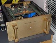
Oh...one more photo for fun: 😎
Attachments
homemodder said:Hannes after seeing that schematic Im shocked, why did he go over to gainclones.😱 😱
Money honey.
He sold out to the digital (chopper) amp faction
Hi ungie,
Looks nice except for the coffee stains on the face plate.
DC offset and bias currents are always measured with no load attached and no signal applied. The amp has to warm up and settle in before taking readings. This typically means the amp is idling for 30 ~ 45 minutes. The other way to do it is to drive the amp into a load until it warms up, then disconnect the input and load and wait until everything stops drifting.
-Chris
anatech said:Hi ungie,
Looks nice except for the coffee stains on the face plate.
DC offset and bias currents are always measured with no load attached and no signal applied. The amp has to warm up and settle in before taking readings. This typically means the amp is idling for 30 ~ 45 minutes. The other way to do it is to drive the amp into a load until it warms up, then disconnect the input and load and wait until everything stops drifting.
-Chris
Unfortunately pictures can be deceiving. 🙁
These amps have had a hard life and the faceplates, handles, and top cover are in bad shape with lots of small scuffs and bumps. The heatsinks also have a few blemishes.
Once I get both up and running and have evaluated the sonics, I'll decide if it's worth the effort of stripping the chassis and having all the parts re-brushed and re-anodized.
Your comments on the offset and bias are noted.
I have no idea why I forgot to disconnect the input!
Hi ungie,
From what I've heard of the preamp I did, they should be worth a complete restoration. Can those marks be buffed out? If not, check how much new ones might be from Jeff Rowland as well. The worst thing you could find out is that they are not available. Next might be a polishing and plating company. One that finishes nice things.
Good luck on restoring those amps.
-Chris
Happens to all of us. Professional or not. No damage was done, just possibly readings that were off a little bit. The bias will be the most affected.I have no idea why I forgot to disconnect the input!
From what I've heard of the preamp I did, they should be worth a complete restoration. Can those marks be buffed out? If not, check how much new ones might be from Jeff Rowland as well. The worst thing you could find out is that they are not available. Next might be a polishing and plating company. One that finishes nice things.
Good luck on restoring those amps.
-Chris
- Status
- Not open for further replies.
- Home
- Amplifiers
- Solid State
- Rowland Research Amplifier Help!