Hi all. I own a Rotel RQ-970BX phono preamp. Its recently developed an issue where after after about 10-20 minutes of playing it emits a big very loud kind of fart noise (sorry but thats the easisest way to describe it) that rapidly drops off in amplitude with loud bang at the end (which isn't great on the ears or the speakers) and then its dead - nothing. Turning it off for a few hours and then back on again it once again plays fine for 10-20 minutes and then same issue. If I just leave it on for an hour with out playing and then play something then its already dead.
Noteably when it is dead it is always dead on both left and right channels.
Im not an audio or electronic expert by any means, but it felt to me like it was probably a capacitor issue of some kind? Does that fit with these symptoms?
If it was one capacitor might that only kill on channel left or right - but not both?
I took the lid off and visually check all the caps for any sign of leaks or swelling but non show any obvious signs.
I though maybe just to try to replace all the caps in the output stages? but there are quite a few and its seems like a bit of work which might not address the issue.
Does anyone have any ideas or advice on this. Getting it repaired professionally is likely to cost more/same as buying another unit.
If this is a know issue that is likely fixable with a couple of cap replacements then Id be happy to try that but not really sure where to start.
Squegging and then tripping the protection? Or perhaps the protection circuit is way out and thermally drifts till it cuts in ungracefully?
Dried out capacitors are a possible cause. How old is the unit?
The other cause that could kill both channels is the power supply - checking that is relatively easy. Thinking about it a preamp seldom has protection circuitry so perhaps the supply?
Dried out capacitors are a possible cause. How old is the unit?
The other cause that could kill both channels is the power supply - checking that is relatively easy. Thinking about it a preamp seldom has protection circuitry so perhaps the supply?
I believe Rotel often puts the schematic in the owners manual. If you have a multi-meter you could test the power supply voltages and trace the signal to see at what stage it stops working. It could be a cracked solder joint that goes open when the chassis warms up.

Thanks all for the input. It was only when I was writing the post that I really twigged that it was both channels that go - so agree it makes sense issue is likely in power stage.
I'll take a look at what I can in the power stage with a multi-meter and the schematic and see if anything is obviously off, or if there is any dramatically changed in alive vs dead state. As tjbox says only a few caps in the power stage so I could look at changing those and see...
Will post back if I get anywhere. Tks all.
Attachments
I used to own one of these, in the late 90's. I don't know how long they made them, but 20 years old is not an unfair assumption. Other Rotel components have had issues with glue around PSU capacitors becoming conductive and causing all kinds of havoc, which could be the case here as well (judging from the pictures). .Dried out capacitors are a possible cause. How old is the unit?
I don't know the age as I only got it a couple of years ago, but yeah must be at least 20 years min, probably more...
A nube question - just to try and understand what Im looking at in the power stage:
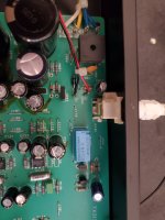
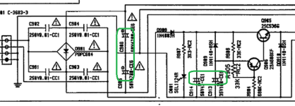
The power stage of the circuit board and schematic seem split into two clear sections.
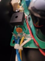
The first is the rectifier section with the big black square rectifier diode and its ceramic caps - I get that part.
Then there is the second section with the big blue rectangular Takamisawa relay and a couple of transistors. What is this section for? Whats with the relay?
A nube question - just to try and understand what Im looking at in the power stage:
The power stage of the circuit board and schematic seem split into two clear sections.
The first is the rectifier section with the big black square rectifier diode and its ceramic caps - I get that part.
Then there is the second section with the big blue rectangular Takamisawa relay and a couple of transistors. What is this section for? Whats with the relay?
Hi since it has Black Gate caps I would leave those in peace for now and start with removal of the glue and checking the whole PSU section plus resoldering all solder joints. What you describe seems voltage cutout. If so it can be measured. Just connect a DMM with clips and monitor the PSU output voltages at C905 and C906 when the fault occurs. What about the power LED? Do you see any change in its brightness when things go wrong? When DC is not the problem measure the transformers secondary AC voltages and check if that one is the one failing. I don't think the separate symmetric PSUs around Q901 ...Q904 are to blame when both channels fail simultaneously.
*It could also be there mains switch but then the power LED should also fade after time. That is eh... its function.
If not capable or not experienced enough or any doubt just don't do anything and have it fixed by a person that does know stuff. This is a simple device not taking much time but it could be a tough cookie.
Last edited:
So I did some measurements with DMM and clips as suggested.
The 4 cap in the power stage C905, C906 and C913, C914 all have a solid ~30v. The amp has been on a while (> 1h) so is assumed to be in failed state - when the amp is powered on the voltage over these caps comes straight up to 30v. I am assuming that means everything is good up to these caps?
The other caps tested after the power stage (C907, C908, C909, C910, C911, C912 and C121, C122) all give wildly fluctuating voltages when the amp is powered on (presumably to failed state) and then give slowly changing low voltages like they are slowly discharging. I don't know if this is normal/expected or not - but feels a bit off.
Im out of my depth now and am not really sure what to test next. My feeling is that the power-stage caps (which would have be easy to replace) actually appear to be good? So the problem is else where which might be beyond my diagnostic capacities? It is odd though that both channels die - as if it was a cap later in the channel amps I expect to loose only a channel. Could it be related to the relay?
Attachments
Measure secondary AC voltage please. Also don’t presume/assume, just measure and be sure to measure when a (verified) fault condition occurs.
We need to know what really happens otherwise we may assume you will manage 😉 We then will presume that is not to your likings.
You do have rails going down but where?
Also: when this device has not had an overhaul and is in original state resoldering all solder joints is the first thing to do.
I also thought about the relay but it only shorts outputs to GND. An error normally causes a shorted output.
Last edited:
Ok I put the circuit board back in place and wired the amp to rest of the rig and powered it up with a record playing and it was in alive state. Typically now this doesn't last very long, so I immediately cut power to the preamp - leaving the turn table and rest of the rig on.
I put DMM on secondary AC voltage over the white ground and one of the blue wires. When I turned the preamp back on - no sound and 22 v AC - during this measurement there was a short growl and then again silence - but during that there no change in voltage - steady 22 v ac. Taking off the DMM to check normal operating conditions it remained in fault mode.
In the validated fault mode I then re checked the DC voltage over cap C914 (accessible with clips from the top of the board) and it was giving steady 29v.
Thanks for your help on this - I am open to trying any other tests if you have any ideas - but don't want to take too much of any ones time. I thought it might be a quick fix (like replace a cap or two) but if its likely to be more complicated I can either take it to repair place or buy a second hand replacement unit - they are likely to be about the same cost...
I put DMM on secondary AC voltage over the white ground and one of the blue wires. When I turned the preamp back on - no sound and 22 v AC - during this measurement there was a short growl and then again silence - but during that there no change in voltage - steady 22 v ac. Taking off the DMM to check normal operating conditions it remained in fault mode.
In the validated fault mode I then re checked the DC voltage over cap C914 (accessible with clips from the top of the board) and it was giving steady 29v.
That sounds like quite a big job - I have done a bit of soldering but its not something I do regularly. I do have a solder sucker and the gear - I could do the power stage I guess. To be honest the soldering underneath the board all looks OK - but Im not an expert..Also: when this device has not had an overhaul and is in original state resoldering all solder joints is the first thing to do.
Thanks for your help on this - I am open to trying any other tests if you have any ideas - but don't want to take too much of any ones time. I thought it might be a quick fix (like replace a cap or two) but if its likely to be more complicated I can either take it to repair place or buy a second hand replacement unit - they are likely to be about the same cost...
Normal maintenance of 15+ years old stuff (without complaints/faults) is:
1. brushing with a brush and vacuum cleaner.
2. cleaning, inside and outside. Also PCB.
3. checking electrolytic caps and replace if they are bad
4. check switches and possibly do maintenance
5. resolder all solder joints
6. remove flux and debri from soldering so clean PCB again
I have dealt with this one before but I really forgot what I did. It is not a big job as it is only a phono preamp. I am not a native speaker so again: you do know it has + and - power supplies and such even with separate transistors per channel? So in fact 2 x +, 2 x - and GND. Are both the + and - rails going down?
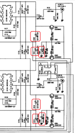
Emitters of Q901 and Q902 are for one channel and Q903 and Q904 for the other channel. In each channel one of the pair (Q901 and Q903) will read a positive voltage and the other one (Q902 and Q904) a negative voltage all with respect to GND. Measured from emitter of Q901 to emitter of Q902 double the previous measured voltage and the same for Q903/Q904.
1. brushing with a brush and vacuum cleaner.
2. cleaning, inside and outside. Also PCB.
3. checking electrolytic caps and replace if they are bad
4. check switches and possibly do maintenance
5. resolder all solder joints
6. remove flux and debri from soldering so clean PCB again
I have dealt with this one before but I really forgot what I did. It is not a big job as it is only a phono preamp. I am not a native speaker so again: you do know it has + and - power supplies and such even with separate transistors per channel? So in fact 2 x +, 2 x - and GND. Are both the + and - rails going down?
Emitters of Q901 and Q902 are for one channel and Q903 and Q904 for the other channel. In each channel one of the pair (Q901 and Q903) will read a positive voltage and the other one (Q902 and Q904) a negative voltage all with respect to GND. Measured from emitter of Q901 to emitter of Q902 double the previous measured voltage and the same for Q903/Q904.
Last edited:
I agree with @jean-paul on the rails theory. You are getting great advice here 🙂
The one check I would do is simply measure the DC voltage on pins 4 and pins 7 on all of the opamps when the fault occurs and see if a rail is going down. Pin 7 should be around +17 volts and pin 4 around -17 volts. The Zener diode voltage references are common to each channel and although unlikely (very unlikely) one could be failing. The voltage check will show what is happening.
Resoldering a board like that takes minutes... honestly. But first look really carefully for any obviously poor joints and tbh voltage measurement is the proper way to fix this. Also tap, poke and prod the board and see if you can make the problem occur. If so that points to a physical issue.
The one check I would do is simply measure the DC voltage on pins 4 and pins 7 on all of the opamps when the fault occurs and see if a rail is going down. Pin 7 should be around +17 volts and pin 4 around -17 volts. The Zener diode voltage references are common to each channel and although unlikely (very unlikely) one could be failing. The voltage check will show what is happening.
That sounds like quite a big job - I have done a bit of soldering but its not something I do regularly.
Resoldering a board like that takes minutes... honestly. But first look really carefully for any obviously poor joints and tbh voltage measurement is the proper way to fix this. Also tap, poke and prod the board and see if you can make the problem occur. If so that points to a physical issue.
Ahem, experience tells that unexperienced people short IC pins while measuring directly at the pins as a standard.
* I do recall the muting relay in this one but I can not find that logically now. Any problem in the relay circuit with voltage going down would have the power LED fading.
* I do recall the muting relay in this one but I can not find that logically now. Any problem in the relay circuit with voltage going down would have the power LED fading.
You could (for starters) spray some contact cleaner into the MM/MC switch, and push it in and out 50 to 100 times (massage),
and see where it takes you. Then reconnect the riaa and try again 😉
and see where it takes you. Then reconnect the riaa and try again 😉
Yeah I can see that would be very easily done 😳 - I'll be careful. Normally I do all clip placement with the power off having waited 5 mins for cap discharge.Ahem, experience tells that unexperienced people short IC pins while measuring directly at the pins as a standard.
Heres a video of IC103 DC volts across pin 4 and GND as the power comes on.
The volume is down on this vid unfortunately so cant hear what the amp is doing.
Attachments
Last edited:
-17.8V to 0V? Definitely rail failure but what about the other supply pin 7? What is the voltage on the 18V Zener diodes?
Please reread suggestions and measure/answer with numbered items. Makes it better to understand also for readers. One can rely on random action but it is better to do systematic approach.
Please reread suggestions and measure/answer with numbered items. Makes it better to understand also for readers. One can rely on random action but it is better to do systematic approach.
Last edited:
I took a second shot of same pin 4 with sound - unfortunately its too large to upload. You can hear each channel go to fault separately (half a second between channels) as soon as the power comes on. Again the voltage stays very low throughout at around -0.3 to -0.4 volts.
I also did pin 7 with volume up. The voltage goes to the expected +16.8 volts and then you hear the left and right channels go to fault - again with a half second separation between each channels faulting. Throughout voltage on pin 7 stays at the expected +16.8 volts. I.e. no voltage change through out the loud burping to fault state.
I also did pin 7 with volume up. The voltage goes to the expected +16.8 volts and then you hear the left and right channels go to fault - again with a half second separation between each channels faulting. Throughout voltage on pin 7 stays at the expected +16.8 volts. I.e. no voltage change through out the loud burping to fault state.
Last edited:
Same behavior for pin 4 and 7 on the other opamp IC104. Pin 4 at -0.3 to -0.4 volts and Pin 7 at +17 volts - throughout loud burp to failure mode on power on.
Vid is pin 7 on IC104. In this vid the voltage is still coming up on pin 7 when it fails but in a previous try on pin 7 the voltage was up steady at 17 volts and just stayed constant throughout the loud burp to failure mode.
Vid is pin 7 on IC104. In this vid the voltage is still coming up on pin 7 when it fails but in a previous try on pin 7 the voltage was up steady at 17 volts and just stayed constant throughout the loud burp to failure mode.
Attachments
IC101 and IC102 similar asymmetry between pin 4 and 7.
both Pin 4s come up slowly (30 seconds) to around +1.5v. Pin 7s both at +17v
Something notable during this test:
At one point having powered off and back on the normally short loud burp became very long and lasted about 30 seconds very slowly dropping off in freq and amplitude. While it was going on I touched different components on the board - notably touching transistor Q102 affected the tone of the burping - like playing an instrument. Unfortunately while doing this the burping stopped and the amp was in failure mode and I couldn't repeat the test. I'll try this again tomorrow when the amp is cold.
There is never fading or change of the red power diode - that remains constant whatever state the amp is in, failure or good.
The most obvious issue seems to be the voltage on pin 4 of all opamps. IC103,104 pin 4 at ~ -0.4volts. IC101,102 pin 4 at +1.5volts (comes up gradually).
Pin 7 seems ok at ~ +17volts on all opamps.
both Pin 4s come up slowly (30 seconds) to around +1.5v. Pin 7s both at +17v
Something notable during this test:
At one point having powered off and back on the normally short loud burp became very long and lasted about 30 seconds very slowly dropping off in freq and amplitude. While it was going on I touched different components on the board - notably touching transistor Q102 affected the tone of the burping - like playing an instrument. Unfortunately while doing this the burping stopped and the amp was in failure mode and I couldn't repeat the test. I'll try this again tomorrow when the amp is cold.
Sorry Im not familiar enough with the diode layout - which Qxxx on the schematic? And how to measure is that a DC voltage across the diode or between one end and gnd? (sorry Im software not electronics...so kind of out of depth)What is the voltage on the 18V Zener diodes?
There is never fading or change of the red power diode - that remains constant whatever state the amp is in, failure or good.
The most obvious issue seems to be the voltage on pin 4 of all opamps. IC103,104 pin 4 at ~ -0.4volts. IC101,102 pin 4 at +1.5volts (comes up gradually).
Pin 7 seems ok at ~ +17volts on all opamps.
- Home
- Source & Line
- Analogue Source
- Rotel RQ-970BX phono preamp issue