A lot to read but I think I get the takeaway point of pin 7 voltage is correct and pin 4 varies between 0 and -17 volts. Both rails should be rock steady.
Suspects are the Zener failing low impedance, the 1k5 going high/open circuit or the electrolytic cap failing short (unlikely but possible). More likely could be a break in the print somewhere so I would check that the raw voltage on the collectors of the two regulators remains at around -25 volts.
If that jumps around to zero then you have a break in the print feeding them.
If it remains then its likely one of the those three parts and the safest fix is to swap them all unless you can definitely identify the problem.

OK sorry for the lack of clarity - Im software not electronics so am a bit lost. Looked a bit more closely at the schematics to understand what people are asking/saying and did a bit of reading - a bit clearer now. I think were very close now 🙂. Heres a hopefully clearer summary:
1. Secondary AC voltage: White to Blue1 22volts good. White to Blue2 22volts good. Blue1 to Blue2 44 volts => Nothing wrong with transfo.
2. Collector voltage into -ve side: Q902 vs gnd correct at -30v and same for Q904 -30v. (Same on +ve side into collector Q903 and Q901 at +30v.) => Nothing wrong with Rectifier.
3. Emitter voltage -ve side Q902 vs grn OFF at -1.5v - it starts lower (-0.6v) and creaps up to that maximum. (Correctly +17v on +ve side on Q903 emitter)
4. Voltage over D907 on -ve side OFF AT -1.5v. (Correct on +ve side D908 at +17v)
So best chance of fix is replace:
I did measured this inplace with ohm-meter with power off and it was in the MOhms (~1.4 MOhm) not the 1.5 k Ohm expected - I'll pull this out and test it out of place later. This would fit with @Mooly's comment:
Thanks so much @jean-paul and everyone for you time and input (sorry for the nube responses, was a bit of a learning curve as really started from zero...)
1. Secondary AC voltage: White to Blue1 22volts good. White to Blue2 22volts good. Blue1 to Blue2 44 volts => Nothing wrong with transfo.
2. Collector voltage into -ve side: Q902 vs gnd correct at -30v and same for Q904 -30v. (Same on +ve side into collector Q903 and Q901 at +30v.) => Nothing wrong with Rectifier.
3. Emitter voltage -ve side Q902 vs grn OFF at -1.5v - it starts lower (-0.6v) and creaps up to that maximum. (Correctly +17v on +ve side on Q903 emitter)
4. Voltage over D907 on -ve side OFF AT -1.5v. (Correct on +ve side D908 at +17v)
So best chance of fix is replace:
- Zener D907
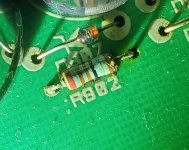
- Resitor R902
- and maybe Cap C906 (visually looks ok)
I did measured this inplace with ohm-meter with power off and it was in the MOhms (~1.4 MOhm) not the 1.5 k Ohm expected - I'll pull this out and test it out of place later. This would fit with @Mooly's comment:
the 1k5 going high/open circuit
Thanks so much @jean-paul and everyone for you time and input (sorry for the nube responses, was a bit of a learning curve as really started from zero...)
OK didn't think to measure the +ve side inplace resistor R901 for comparison 🤦♂️- I did that just now and its a reliable 1.5 k Ohm as expected. R902 is just all over the place in comparison.
So I think it is a dead R902 - that should be an easy and cheap fix!!
Will get that sorted asap and report back. Thanks again all, your guidance and expertise much appreciated - amazed to find this community so responsive and helpful 🙂
So I think it is a dead R902 - that should be an easy and cheap fix!!
Will get that sorted asap and report back. Thanks again all, your guidance and expertise much appreciated - amazed to find this community so responsive and helpful 🙂
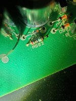
Looking at that R902 now with that knowledge it is pretty clearly fried... I had in my head a cap issue so looked at those carefully - I should have done a closer visual inspection of everything... Anyway pretty clear now I think this is the culprit.
Attachments
The diodes to the right look slightly corroded as well. Did you clean off al the glue that was used to hold the caps in place? Rotel equipment from this era did have problems with that glue.
You have to at least isolate one end to get an accurate reading. Interaction with other parts and slight residual voltage (charge) on caps really confuse readings in circuit. Also even lead ploarity alters things as one way round will round on transistors and diodes and the other way will not. So always isolate as a general rule.Can I measure the power-off resistance across R902 inplace - or is only an out of place measurement reliable?
Tbh that points to a break in the print. If the collector volts is low and yet the voltage on the big reservoir cap is OK (C906) then there is a break.3. Emitter voltage -ve side Q902 vs grn OFF at -1.5v - it starts lower (-0.6v) and creaps up to that maximum. (Correctly +17v on +ve side on Q903 emitter)
Yes when I took out the cooked resistor there was literally a black burn mark on the board - space between board and resistor a good idea. As it happens with my sloppy component mounting I have that now more or less by accident 😆It seems it got warm. The new one could be soldered with a few mm space below it. Maybe replace the other one too.
Worth noting that visually by eye the resistor looked kind of OK - certainly didn't jump out. But looking at the zoomed photo from phone is was quite clear it was damaged.
Next time I face something like this I'll:
a. Not make assumptions when I don't really know what Im doing (e.g. thinking it was electrolyte caps)
b. Photograph the board and examine it on PC, zoomed, component by component.
This would have likely found this with out the electronics diag. If you know what your doing I guess the electronics diag is quick and relatively easy but for someone without the knowledge the closeup visual inspection is a good tool.
Its nice to have analog back, it was worth the effort 🙂
Attachments
Resistors can and do fail. Its worth you noting there is another identical resistor feeding the positive regulator Zener reference diode.
For continued trouble free operation indeed replace both for (preferably) slightly higher power rated ones and replace the Zener diodes too. Mount both 2 or 3 mm elevated for better air flow.
This way it will be unlikely that it fails again. Failure is a result of slight heat + age.
This way it will be unlikely that it fails again. Failure is a result of slight heat + age.
Last edited:
I wonder what the raw DC is. I'm guessing around 30 volts given the 50 volt cap ratings which puts dissipation around 0.1 watt. If it were 40 volt then that goes up to nearly 0.4 watt.
- Home
- Source & Line
- Analogue Source
- Rotel RQ-970BX phono preamp issue