Bit the bullet and testing?
Well, I bit the bullet, installed a 16.xx MHz crystal and the comparator.
The comparator is not running hot (or even warm).
Is there any way (aside from plugging into my beloved Rotel) to determine whether or not it's working properly?
The only equipment I have is a Fluke 187 DMM.
I'm not looking for scope measurements, square waves or other such things. I'm just looking for a simple way of knowing whether or not its doing what it should. (and won't blow up my CDP)
Thanks.
🙂
If you meassure the output of the clock with a multimeter set to DC it should interpret the squarewave...that is if there is one.. as ~ 2,5V
Re: Bit the bullet and testing?
Hi, It won't blow up your CDP as there is a output-coupling cap in the clock. Best way of testing it is to connect.
If your powersupply is reading +5V it's OK.
ozone_stink said:Well, I bit the bullet, installed a 16.xx MHz crystal and the comparator.
The comparator is not running hot (or even warm).
Is there any way (aside from plugging into my beloved Rotel) to determine whether or not it's working properly?
The only equipment I have is a Fluke 187 DMM.
I'm not looking for scope measurements, square waves or other such things. I'm just looking for a simple way of knowing whether or not its doing what it should. (and won't blow up my CDP)
Thanks.
🙂
Hi, It won't blow up your CDP as there is a output-coupling cap in the clock. Best way of testing it is to connect.
If your powersupply is reading +5V it's OK.
getting a little discouraged
Well, I connected the DMM to the clock out and I get ~0.0V
It reliably starts at 1.1V and works its way down to 0 in about 4 seconds.
I'm using a +9V 120mA DC test power source.
I've gone over the schematics and checked for solder bridges many many times...
Well, I connected the DMM to the clock out and I get ~0.0V
It reliably starts at 1.1V and works its way down to 0 in about 4 seconds.
I'm using a +9V 120mA DC test power source.
I've gone over the schematics and checked for solder bridges many many times...
I'll try it in the CDP... I guess that can't hurt.
Does it take stupendous incompetance to fry a crystal or is it relatively easy with a soldering iron? I'd hate to wreck my CDP when I've got a couple of days off before work!! 😉
Does it take stupendous incompetance to fry a crystal or is it relatively easy with a soldering iron? I'd hate to wreck my CDP when I've got a couple of days off before work!! 😉
Well, I connected it up to my CDP and the thing started acting as if there were no crystal or clock at all. (no read disc, lense swings to one extreme, etc...)
I tested by plugging in a Trichord 2 to the same solder points and it works.
For the moment, I still have the trichord plugged into the player and I think I would need to listen to it longer to be able to discern any difference.
I've removed R631 and am using clock output on the pad closest to pin 1 of the TC74HCU04AP (U631 Inverter).
I'm getting power from the +ve pad of C907 (C907 retained, of course)
Ground is coming from -ve pad of C633 (C633 & C634 removed)
The original crystal (X631) was removed and added to the Kwak Clock.
I'm seriously thinking of desoldering everything on the board and starting over or doing it P2P. Maybe I wrecked a solder track or something....
Other things I did, since I had the cover off:
Bypassed C741, C742, C743, C744 with 10uF Tant. caps. I believe these caps are decoupling caps for the op-amps. I remember reading on
Zero Distortionn That Dejan says Tants are not suitable in audio except for use as decoupling caps.
I'm not sure if I've made a mistake in my understanding of what C741-C744 are doing, or else I've most likely erred in performing this mod. -Any opinions on this are welcome.
I also couldn't resist replacing the DC blocking caps C717 & C718 (100uF 25V panasonic FC) with 100uF 100V Elna Cerafines. (I have a few of the Elna's on hand). I hope this mod. hasn't made things worse. -How would one check for DC offset properly? Should I poke my Fluke into the +ve side of the DC blocking caps and check for DC? Perhaps I can later rip these caps out completely.
Finally, I bypassed the C631 (22uF 20V Sany Oscon) with 3 0.1uF X7R caps. -This was in the spirit of improving decoupling by this cap. for the TC74HCU04AP (advice I received from another generous sort).
Well, I won't give up on the Kwak Clock because:
1 - I expect that it will sound better than Trichord 2
2 - I would like to learn something from this
3 - I would also like to help other n00bs to not repeat my mistake(s)
4 - Elso has been tremendously helpful in email and forums for giving me good advice on how to hook it up and debug it. I feel that it would be insulting to him if I simply give up on it.
P.S. the listening I did last night where I couldn't hear much of a difference was with all the above mentioned mods.
Well thanks for all the help / advice so far....
🙂
I have been listening more and more to the player and it sounds like I have actually made things worse with the mods. I suspect it's those Tantalum caps. They're coming out tonight and then I'll give another listen.
I am also planning to do the Swenson Mod on this unit. I may lose some (artificial?) bass "slam" from the op-amp circuits, but I will likely gain in terms of clarity.
My Marantz 2285b receiver has a 33K ohm impedance, so I think that works out to .56uF caps between the DAC and the RCAs. -Any opinions on this are welcome, of course.
As I live in Montreal, Solen Electronique is right around the corner from me, so I can get the 'boutique parts' cheap.
Well, that's it for now.
Well, not much to report. The Tants are gone and the sound seems better, though I must confess that this may be purely psychological at this point. -That and the cats aren't running away from Richie Hawtin anymore... 
meh.
Since I'm using an unmodified Trichord, I believe that there'll be loads of room for improvement when I get Elso's clock to work. (pi filters and better design and all)
meh.
Since I'm using an unmodified Trichord, I believe that there'll be loads of room for improvement when I get Elso's clock to work. (pi filters and better design and all)
Ripping out the clock inverter (HCU04)
It seems almost universal on these forums that the HCU04 is more likely to muck up your clocking and _add_ jitter than do anything good.
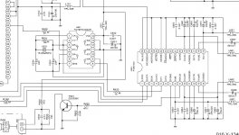
So, I'd like to rip it out. Problem is I'm not sure how. Here's an experiment with me trying to attach an image of the HCU04 in circuit with my Rotel:
It seems almost universal on these forums that the HCU04 is more likely to muck up your clocking and _add_ jitter than do anything good.
So, I'd like to rip it out. Problem is I'm not sure how. Here's an experiment with me trying to attach an image of the HCU04 in circuit with my Rotel:
Attachments
More on HCU04
So, would I just run a couple of wires from my clock out to R635 (to Controller Chip) and R633 (DAC XTI)? -Then float the HCU04 off the board?
Or is it more complicated (different) than that?
Thanks for the help!! 🙂
So, would I just run a couple of wires from my clock out to R635 (to Controller Chip) and R633 (DAC XTI)? -Then float the HCU04 off the board?
Or is it more complicated (different) than that?
Thanks for the help!! 🙂
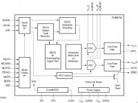
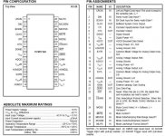
PCM1732 DAC & Swenson Mod
The PCM1732 is a single-ended voltage out DAC. You can download the datasheet here.
A few posts back, I linked to Swenson's page that describes the mod.
I'm plugging my CDP into a Marantz 2285B that has integrated pre-amp with a 33K Ohms input impedance. John recommends a 0.47uF cap if you've got a 50K input impedance and a 4uF if your at 10K impedance. He advises to pick something in between if your impedance is in between. -I have a funny feeling this is not linear, but not knowing any better, I selected a cap of 0.56uF.
If anybody can tell me whether or not 0.56uF is wrong and why (or what it should be), I'd be much obliged.
The whole reason I'm thinking of doing this mod. is to eliminate the op-amps and dc-blocking caps (and anything else) that will be adding crap to the signals coming from the DAC. -Am I wrong to do this? Perhaps this is just a bad idea for my design. -I'll give it a try and a listen, but somebody on this site surely knows...
The PCM1732 schematic is attached.
Attachments
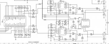
DAC in RCD-02 circuit
Finally, here's what Rotel have done with the DAC...
Seems like they've gone to some trouble to implement the analogue stage with filtering and such... As far as I know, they don't tend to put lots of extra stuff for no reason...so this is why I'm questioning the value in performing the Swenson mod. in this unit.
If (when) I do go ahead, I would lift the pads of C667 & C668 and run a wire from there to the RCA outs. The ground on RCAs, I would run to nearest ground (existing RCA grounds, for example?).
more comments & suggestions welcome...
Attachments
Oh.....it is one of those kind of oscillators........
Kill "2" and "4". Take those 2 resisitors that feed the world from "1". That will help some.
There are other oscillators besides Elso's. He may not thnk so. [joke]
Jocko
Kill "2" and "4". Take those 2 resisitors that feed the world from "1". That will help some.
There are other oscillators besides Elso's. He may not thnk so. [joke]
Jocko
Re: Oh.....it is one of those kind of oscillators........
Hi Thanks!! ^I have understood this to mean that I should cut the tracks leading to pin 2 and pin 4 of the HCU04. Then I should run R635 and R633 to pin1 of HCU04.
Is that what you meant? Am I going in the right direction even? 😉
(If this feels like: "Ask a stupid question, get a....", it's not deliberate).
Jocko Homo said:Kill "2" and "4". Take those 2 resisitors that feed the world from "1". That will help some.
There are other oscillators besides Elso's. He may not thnk so. [joke]
Jocko
Hi Thanks!! ^I have understood this to mean that I should cut the tracks leading to pin 2 and pin 4 of the HCU04. Then I should run R635 and R633 to pin1 of HCU04.
Is that what you meant? Am I going in the right direction even? 😉
(If this feels like: "Ask a stupid question, get a....", it's not deliberate).
I live in Canada
I've got a whole army of squirrels in my backyard!! They're up to something....
My cats can feel it too. 😱
I've got a whole army of squirrels in my backyard!! They're up to something....
My cats can feel it too. 😱
Nein!!!!!!!
I meant the gates with those numbers on the schematic..........!
You will have to then tie the inputs to them either high or low.
Starting to make sense?
Maybe I need to change my avatar to John Cleese, standing in water up to his knees, asking what is wrong if he eats squirrel now and then.
BTW..........that strange B-B DAC chip looks like they do the combining inside, so your cap mod should be ok. Providing you can deal with Solen.
Jocko
Well, I tried that Cap mod (aka Swenson) last night.
-1- I used the grounds from the original RCAs
-2- I ran single strand of Cat5 from grounds to new Gold RCA -ve (gnd.)
-3- I yanked caps 667 & 668
-4- I ran a single strand (1/8) Cat5 from +ve pads where C667 & C668 were to Solen 0.56uF 630V caps.
-5- I soldered the other side of each Solen cap to the center pin of new gold RCA jacks.
-6- I ran a 300pF 500V mica cap from center pin to -ve housing on new gold RCAs.
-7- I measured AC voltage with a CD when all was done. As expected, the voltage was significantly less than with the op-amps. Interestingly, though, the DC didn't stay at 0. I saw it fluctuate from -0.3V to +1V over the limited time I took the readings.
After this I plugged the CDP into my Marantz to have a listen. -It sounded thin and for lack of a better word awful. Any sense of 3D was lost. In fact, I couldn't rip it all apart and put it back the way it was fast enough.
I suspect that something was 'not right'. Maybe the Solen was the wrong value. Maybe using the old RCA gnds was not so bright. Who knows. However, unless somebody has a really convincing suggestion, I suspect I won't be trying this again.
Well, there's still the clock. 🙂
- Status
- Not open for further replies.
- Home
- Source & Line
- Digital Source
- Rotel RCD-02 Mods