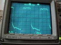
I just disconnected the cells from the clock, and the waveform stopped in 2 seconds.
I remember you told that this clock uses 7mA. Souldn't it last longer with 4400uF per rail?
I remember you told that this clock uses 7mA. Souldn't it last longer with 4400uF per rail?
Exercise
It is left as a nice excerise to the reader to calculate how long the clock will run on these caps after power down......
😉
Bricolo said:I just disconnected the cells from the clock, and the waveform stopped in 2 seconds.
I remember you told that this clock uses 7mA. Souldn't it last longer with 4400uF per rail?
It is left as a nice excerise to the reader to calculate how long the clock will run on these caps after power down......
😉
The reader doesn't have all the elements to calculate this 😉
at what voltage does the oscillator stop?
at what voltage does the oscillator stop?
Horowitz
You do have Horowitz at hand? I have no answer to second question.
Bricolo said:The reader doesn't have all the elements to calculate this 😉
at what voltage does the oscillator stop?
You do have Horowitz at hand? I have no answer to second question.
It's under my eyes, opened at chapter 5
BTW, I found nothinc called Kwak-Clock in the Horowitz 😉
There's the pierce and the colpitts oscillators that look more or less like yours, but not very close.
Yours is like a colpitts ocsillator, but with the cristal between the fet's gate and ground, rather than between Vdd and ground, and without the coupling cap.
It it based on something existing, or did you invent this configuration?
Square Wave
http://www.diyaudio.com/forums/showthread.php?postid=285133#post285133
Yes on this forum by Andrea:Bricolo said:OK, thanks 😉
BTW, did someone else post picture of the squarewave he got with a KC?
http://www.diyaudio.com/forums/showthread.php?postid=285133#post285133
Re: Square Wave
his squarewave looks better than mine
Elso Kwak said:
his squarewave looks better than mine
Discharge Curve
I meant of course the discharge curve of a large electolytic cap.(page 23).

Hi Bricolo, are you kidding, <<vous me prenez pour un fou?>>Bricolo said:It's under my eyes, opened at chapter 5
BTW, I found nothinc called Kwak-Clock in the Horowitz 😉
There's the pierce and the colpitts oscillators that look more or less like yours, but not very close.
Yours is like a colpitts ocsillator, but with the cristal between the fet's gate and ground, rather than between Vdd and ground, and without the coupling cap.
It it based on something existing, or did you invent this configuration?
I meant of course the discharge curve of a large electolytic cap.(page 23).
Re: Re: Square Wave
Don't think so. Andrea has more wiggle on the lower portion.
But again this is not important. I did not find any relation between sound quality and wave form.
Bricolo said:
his squarewave looks better than mine
Don't think so. Andrea has more wiggle on the lower portion.
But again this is not important. I did not find any relation between sound quality and wave form.
Re: Discharge Curve
ok 😉
I haven't looked in the Horowitz for this now, but that's how I think it would be:
the capacitor's voltage decrease with an linear rule (since I assumed that the current was constant)
-so the 1st cap's voltage will slowly drop from 9V (in my case) to zero. During the time it varies from 9 to 5 + the BJT's saturation voltage, nothing will change at the regulated output
-then, the regulated voltage will also fall
but with the amount of capacitance on the board, I thought that this would be longer than 2 secs
Elso Kwak said:
Hi Bricolo, are you kidding, <<vous me prenez pour un fou?>>
I meant of course the discharge curve of a large electolytic cap.(page 23).
ok 😉
I haven't looked in the Horowitz for this now, but that's how I think it would be:
the capacitor's voltage decrease with an linear rule (since I assumed that the current was constant)
-so the 1st cap's voltage will slowly drop from 9V (in my case) to zero. During the time it varies from 9 to 5 + the BJT's saturation voltage, nothing will change at the regulated output
-then, the regulated voltage will also fall
but with the amount of capacitance on the board, I thought that this would be longer than 2 secs
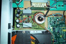
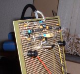
and a general view of the player. All that's left now is to replace the signal and ground cables with a twisted pair. Sounds nice already though. Just one problem is it's sensitive to mains interfierence, which throws the cdp into a static sound for some reason, which only goes if you turn it off for a few minutes and then back on. It's not too much of a problem, just a bit annoying having to remember to be careful.
Thanks again elso! it works!!
Steve
Thanks again elso! it works!!
Steve
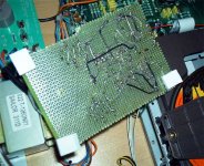
Attachments

Just an idea,
I'm curious to see how the squarewave looks like without a hefty load.
Can't we just make a probe with a higher impedance transmission line? A 75Ohm coax may also be too low, but something like a twisted pair, or a twin lead
I'm curious to see how the squarewave looks like without a hefty load.
Can't we just make a probe with a higher impedance transmission line? A 75Ohm coax may also be too low, but something like a twisted pair, or a twin lead
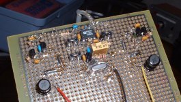

I wish I had more room in my cdp! My housemates Roksan has soooo much more room! Still looks really nice though Bricolo. For some reason it never occured to me to mount the resistors vertically like yours. 🙁 Incedently, with all this talk about loads, the only way this clock would work is if the 1K test resistor is still in place where the original crystal used to be. If It's removed, the transport doesn't go mad or anything, just, nothing.... I tried mounting the 1k resistor on the matrix board, but that didn't work and again the transport did nothing. Is there a reason why on a long cable run (due to overly cramped in cdp) having a 1k termination helps? Maybe this is because i couldnt set up on a scope, and just set pin 3 to 0.55v? Maybe worth trying another value between the range of 0.5 and 0.6v?
I just had another thought as well, could the unreliability I talked about earlier be caused by the ground of the kwak clock (incl its own power supply) is directly coupled to the cdp ground (where the caps around the crystal used to be). Would it be worth putting a decoupling cap in between, like on the output perhaps?
Either way I have to say that when this is working (which is all the time now I know what I can and can't unplug with the cdp on, btw the kwak clocks power supply is run off the raw mains supply into the cdp, so it runs constantly regardless of whether the cdp circuits are on or off) it's sounding really good! I'm thinking the original oscillator must have been pretty bad, as sounstaging is on a different level from what I can hear, and high frequencies sound a lot cleaner and defined. I don't know if this is what most people experience with a clock upgrade.
Thanks,
Steve
- Status
- Not open for further replies.
- Home
- Source & Line
- Digital Source
- Rotel RCD-02 Kwak-Clock upgrade