Ok here's the story...You need to connect the test speaker between gnd and amplifier's out before relay .Use an electrolytic in series as explained.
The underside of the device for which I was hoping to hook up wire and run through a cap onto a speaker like you said its impossible due to case restrictions covering the two relays. On the other hand I cannot run the amp outside its case as I ll have to make extensions for power, logic and all that.
So the action on this task will be to check for output on the emitters ?
emitters or emitter resistors should be well before the relays, so emitter and ground via a cap onto speakers should be fine.
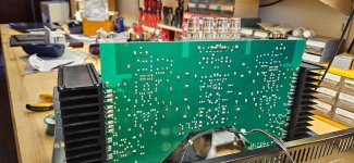
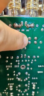
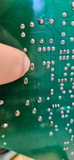
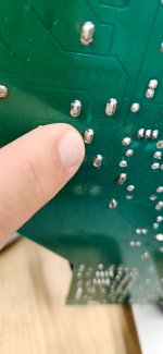
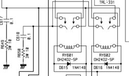
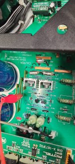
However on the PCB as you may have noticed there are are bus bars (Thick and long copper strips) which I indicate on my pics and are accessible from the component side of the PCB (power supply voltage). The same strips are installed from the output pairs (Emitters or emitter resistors better) onto relay contact (N.O or N.C). So I will be able to access output from those bus bars.
These are marked as JP13 and JP14 as you can see from my pictures of the TOP Side of the amp PCB.
I have to put back though and secure onto chassis the PCB's otherwise am tampering the integrity of the device and myself as a whole. Please see my pictures attached below.
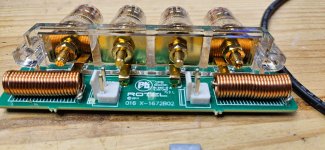
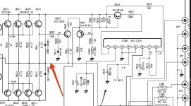
Also since I removed the PCB, I spare some time and checked the whole Zobel Network which components are 100nF and 10ohms resistors for leakage. These are fine. From the circuit of 1070, that I took as a reference, these are indicated below also in the circuit diagram as well as in the same diagram in a previous post.
However on the PCB as you may have noticed there are are bus bars (Thick and long copper strips) which I indicate on my pics and are accessible from the component side of the PCB (power supply voltage). The same strips are installed from the output pairs (Emitters or emitter resistors better) onto relay contact (N.O or N.C). So I will be able to access output from those bus bars.
These are marked as JP13 and JP14 as you can see from my pictures of the TOP Side of the amp PCB.
I have to put back though and secure onto chassis the PCB's otherwise am tampering the integrity of the device and myself as a whole. Please see my pictures attached below.
Also since I removed the PCB, I spare some time and checked the whole Zobel Network which components are 100nF and 10ohms resistors for leakage. These are fine. From the circuit of 1070, that I took as a reference, these are indicated below also in the circuit diagram as well as in the same diagram in a previous post.
Attachments
-
 20241008_115827.jpg437.2 KB · Views: 55
 -
 20241008_090906.jpg429.6 KB · Views: 52
 -
 20241008_090910.jpg325.7 KB · Views: 57
 -
 20241008_090915.jpg414.9 KB · Views: 55
 -
 20241008_090924.jpg305.5 KB · Views: 52
 -
 20241008_090932.jpg336.1 KB · Views: 60
 -
 20241008_090946.jpg226.4 KB · Views: 57
 -
 20241008_091038.jpg353.5 KB · Views: 58
 -
 20241008_091102.jpg309.3 KB · Views: 54
 -
 Capture1.JPG23 KB · Views: 58
Sorry, I dont currently have any music source. So I will use SG and scope, or speaker via an Electrolytic cap.I would prefer another source playing music.
Yes I will send all that immediately after Thimios request. But I remember I did sent sth over this. Not a prob we can do it again.That will most probably be the implementation in your unit.
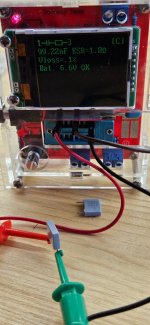
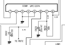
Need Vdc at each of your pins so we can make an assessment on whether your IC is a cloned uPC1237. Pin 1 and 2 are of most interest. A good GND pin is also needed.
Gnd I use the chassis GND which is Phono GND used as a screw onto chassis.
Yeah we can do that
Hello yes I found what the problem was. I was apparently using the wrong ground. Cause if you use the regulator ground (Middle pin) and output both measure ok 5v and 3.29 Volts So ground here is the digital one and not the chassis gnd. But these regulators do not show up on the 1070- schematic. Only the 5V one shows upIn post 26 you were describing trouble with 5V and 3.3V regulators. Did you get that issue resolved to your satisfaction?
Last edited:
Yes ! I willATTENTION!
Because coils is after relays,you NEED to measure for d.c presence BEFORE relays!
Ok coming back for the test of any DC before the relays. The pictures indicate my attachments.
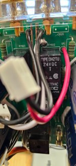
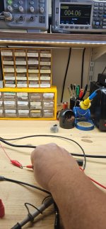
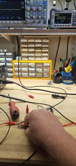
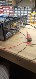
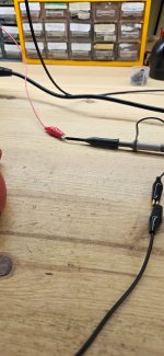
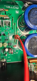
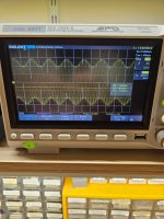
Red Crocodile clips on JP13 and JP14 Bus Bars their origin is on the Emitter Resistors and end up on one point of the relay. The other end of the relay terminates on speaker Posts. NO DC is apparent not even AC (Original 1KHZ @ 100mv) sinusoidal audio, and as one can see from the pics my Scope is at AC Coupling. Also measure the Crocodile voltages and only mV are present Similar to the scope output but with 50Hz signal. So no audio, no dc no ac there. Also one can see my Ground point which is basically Chassis Ground. I have also test the Negative post of the speakers output for my measurements to no avail.
Red Crocodile clips on JP13 and JP14 Bus Bars their origin is on the Emitter Resistors and end up on one point of the relay. The other end of the relay terminates on speaker Posts. NO DC is apparent not even AC (Original 1KHZ @ 100mv) sinusoidal audio, and as one can see from the pics my Scope is at AC Coupling. Also measure the Crocodile voltages and only mV are present Similar to the scope output but with 50Hz signal. So no audio, no dc no ac there. Also one can see my Ground point which is basically Chassis Ground. I have also test the Negative post of the speakers output for my measurements to no avail.
Attachments
-
 20241008_142825.jpg385.1 KB · Views: 34
 -
 20241008_142814.jpg416.1 KB · Views: 33
 -
 20241008_142723.jpg375.9 KB · Views: 40
 -
 20241008_142753.jpg355 KB · Views: 39
 -
 20241008_142658.jpg356.3 KB · Views: 37
 -
 20241008_142645.jpg334.6 KB · Views: 41
 -
 20241008_142617.jpg382.6 KB · Views: 39
 -
 20241008_142601.jpg297.1 KB · Views: 33
No same issue. as soon as you press either of Speaker Set switch, you hear the relay kicking in and in split second amp in ProtectionIn comment 4, you indicate you have to switch off both A and B speakers to avoid tripping protection. If you disconnected the speakers, would you be able to activate both A and B relays without triggering protection?
ok here they are. Both Speaker sets are off. I have no other option. Read my last post as to why. First Checking pins of IC if connected to ground as per 1070-diagram. Indeed Pins 3 and 5 are shorted together and both to groundThat will most probably be the implementation in your unit.
Need Vdc at each of your pins so we can make an assessment on whether your IC is a cloned uPC1237. Pin 1 and 2 are of most interest. A good GND pin is also needed.
uPC1237
======
Pin 1= 0V
Pin 2= 0V
Pin 3=Ground
Pin 4=2.3V
Pin 5=Ground
Pin 6=0.74v
Pin 7=2.2
Pin 8=3.3v
Attachments
Last edited:
Good morning all.
Today i used my sg and my headphones. Connect my headphones to headphone socket on amp. Then got my sg connected to the amplifier input terminals ( which are the small white twrminals found on the amp board) and I had audio output. Am under tge impeession now that the amp board is ok as far as no shorts bias etc. For some reason which remains to be seen I got amp protection when either speaker set is pressed. Also I dont have audio on those grey audio cables running from logic or I/O board onto the amp input (which I refered to them as being short) no matter what input I use ans tgen select from the panel. So I suspect that the protection circuitry is also telling tge logic or I/O board to shut down all outputs to amp as well via those short cables or other means.
Today i used my sg and my headphones. Connect my headphones to headphone socket on amp. Then got my sg connected to the amplifier input terminals ( which are the small white twrminals found on the amp board) and I had audio output. Am under tge impeession now that the amp board is ok as far as no shorts bias etc. For some reason which remains to be seen I got amp protection when either speaker set is pressed. Also I dont have audio on those grey audio cables running from logic or I/O board onto the amp input (which I refered to them as being short) no matter what input I use ans tgen select from the panel. So I suspect that the protection circuitry is also telling tge logic or I/O board to shut down all outputs to amp as well via those short cables or other means.

Last update:-
1. Connect a speaker between Ground and Emitter Resistors (any of the 6 will do)
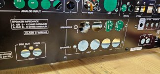
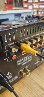
2. Insert SG 1KHz 200mv 0dB on the back of Amplifier where it says "Main-in". I have previously removed the gold iron loop connecting "Pre-out" and "Main-in"
3. I got Amplified 1KHz sound coming out from speaker and with the aid of Scope I can see that its 2V Pk-Pk so the amplifier works,
4. I have tried this on the other channel as well. Similar results
5. Indeed setting the scope on DC Couple there is a negative DC offset on output signal as I can see on scope.
6. I used an Electrolytic in series and that eliminated this offset
Great progress. Now still have not been able to find out as to why is tripping every time I press the Speaker Set button(s) therefore no output from speakers via the relays and also I don't understand yet why there is no audio signal anywhere
along its path to the AMP-in or main -in.😏
I need that manual🙂
1. Connect a speaker between Ground and Emitter Resistors (any of the 6 will do)
2. Insert SG 1KHz 200mv 0dB on the back of Amplifier where it says "Main-in". I have previously removed the gold iron loop connecting "Pre-out" and "Main-in"
3. I got Amplified 1KHz sound coming out from speaker and with the aid of Scope I can see that its 2V Pk-Pk so the amplifier works,
4. I have tried this on the other channel as well. Similar results
5. Indeed setting the scope on DC Couple there is a negative DC offset on output signal as I can see on scope.
6. I used an Electrolytic in series and that eliminated this offset
Great progress. Now still have not been able to find out as to why is tripping every time I press the Speaker Set button(s) therefore no output from speakers via the relays and also I don't understand yet why there is no audio signal anywhere
along its path to the AMP-in or main -in.😏
I need that manual🙂
“5. Indeed setting the scope on DC Couple there is a negative DC offset on output signal as I can see on scope.”
There should the be very little DC offset on the amp output—- less than 100mV. How much DC do you observe? Does DC offset grow with signal amplitude?
Another check: with A and B speaker relays off, confirm there’s open circuit seen across speaker binding posts—— no DC and very large resistance seen with ohmmeter.
HelloThere should the be very little DC offset on the amp output—- less than 100mV. How much DC do you observe? Does DC offset grow with signal amplitude?
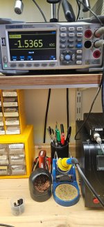
Repeating the same setup as this morning with 1KHZ 200mV @0db I get:
Left Channel=-1.5562v
Right Channel=-1.5562v
That's not normal from what you are expressing here BSST.
No it does not grow with signal amplitude.
These measurements were almost -5mv and almost -2mv just before todays troubleshooting.
I have noted these measurements days ago with a marker on the PCB. Check my pics below that verify that. I don't know why these measure differently now. Always measured with respect to ground.
This Amp is very strange !
Big thank you to you and the rest for your persistence with this and myself. Am also attaching a small video and another picture indicating some sort of an oscillation. It appears to me as being modulated (AM) 🙂
Another check: with A and B speaker relays off, confirm there’s open circuit seen across speaker binding posts—— no DC and very large resistance seen with ohmmeter.
Binding Posts
=========
Speaker, Relays off, (Resistance is measured with power off)
=======================================
Set A L=0V Resistance between Binding Posts= Open circuit
Set A R=0V Resistance between Binding Posts= Open Circuit
-----------------------------------------------------
Set B L=0V Resistance between Binding Posts= Open Circuit
Set B R=0V Resistance between Binding Posts= Open Circuit
Attachments
Last edited:
Sorry,now I'm completely lost.
Please,don't measure for d.c presence when amplifier have a signal input.
Always measure for d.c OUT when INPUT shorted.
I read somewhere that as soon as protection activated,a service shop only can reset it!
Has the protection i.c any connection with microcontroller?
Please,don't measure for d.c presence when amplifier have a signal input.
Always measure for d.c OUT when INPUT shorted.
I read somewhere that as soon as protection activated,a service shop only can reset it!
Has the protection i.c any connection with microcontroller?
Last edited:
Hi Thimios,Please, don't measure for d.c presence when amplifier have a signal input.
That's correct I did not measure for DC presence while Audio input connected to amp. I measured it with no audio input active at that moment.
"Always measure for d.c OUT when INPUT shorted." --> I did just that
"I read somewhere that as soon as protection activated, a service shop only can reset it!" Oh That's not convenient, and certainly not smart ! You mean for Rotel or some other brand ?
I see that the plug am using to reset AMP Protection is situated close to the ARM Microprocessor but not sure about that..
It's possible your DVM is being overloading by presence of large AC and misreporting DCV.
Easiest is to measure with scope with signal applied, with DC coupling of scope. There should not any shift of DC component with presence of AC. Shifting DC in presence of AC may suggest a distortion mechanism.
It's also reasonable to look for DC offset with a DVM with signal present if you are certain the meter can suppress the overlaying AC. The safest approach is to apply a low pass filter in front of the meter, eg 100K in series, 1uF shunt to ground. This suppresses AC, allowing accurate measurement of small DC offset error.
Last edited:
I missed this earlier:
Binding Posts
=========
Speaker, Relays off, (Resistance is measured with power off)
=======================================
Set A L=0V Resistance between Binding Posts= Open circuit
Set A R=0V Resistance between Binding Posts= Open Circuit
-----------------------------------------------------
Set B L=0V Resistance between Binding Posts= Open Circuit
Set B R=0V Resistance between Binding Posts= Open Circuit
You should conduct this test with power applied. The thought is that perhaps there’s some faulty path to the speaker binding posts. With speaker relays off, there should be no voltage present at speaker terminals. But with power on, perhaps a spurious path would be revealed. This is a longshot idea, but an easy test.
In an earlier post you mentioned that even with speakers disconnected, enabling speaker relays triggered protection. This shouldn’t happen. I believe this behavior presents a troubleshooting opportunity. Why does connecting this path that ostensibly has no loading provoke protection?
Another check: with A and B speaker relays off, confirm there’s open circuit seen across speaker binding posts—— no DC and very large resistance seen with ohmmeter.
Binding Posts
=========
Speaker, Relays off, (Resistance is measured with power off)
=======================================
Set A L=0V Resistance between Binding Posts= Open circuit
Set A R=0V Resistance between Binding Posts= Open Circuit
-----------------------------------------------------
Set B L=0V Resistance between Binding Posts= Open Circuit
Set B R=0V Resistance between Binding Posts= Open Circuit
You should conduct this test with power applied. The thought is that perhaps there’s some faulty path to the speaker binding posts. With speaker relays off, there should be no voltage present at speaker terminals. But with power on, perhaps a spurious path would be revealed. This is a longshot idea, but an easy test.
In an earlier post you mentioned that even with speakers disconnected, enabling speaker relays triggered protection. This shouldn’t happen. I believe this behavior presents a troubleshooting opportunity. Why does connecting this path that ostensibly has no loading provoke protection?
- Home
- Amplifiers
- Solid State
- Rotel 1570 AMP in Protection mode!