I take it you were looking for the "I got the service manual" as good news and that you did not actually get it?I think these are just about good news I got !
!! I got the service manual !!!
The email(s) I got back from them seemed to indicate a desire to help out troubleshooting, though it might be a describe the problem and "oh, you need to send that in" type of response. The other email I received was from a Finesounds America (finesounds.zendesk.com):
Hello,
unfortunately we don't send schematics/technical manuals out to end users. What's the problem with the unit?
Much appreciated and sorry for all the pain caused ! In the mean time I have the manual. I will post it on this forum for others to useMy latest attempt has been frustrating. I called the only phone number offered, was dierected via selection menu to a support department. Eventually a voice meeage came instructed me to use web site to make inquiry.
I got automated reply, but no follow up so far. I went down this path in an earlier attempt. It was a black hole—- no further actively.

Here is the Service Manual for Rotel RA1570I take it you were looking for the "I got the service manual" as good news and that you did not actually get it?
The email(s) I got back from them seemed to indicate a desire to help out troubleshooting, though it might be a describe the problem and "oh, you need to send that in" type of response. The other email I received was from a Finesounds America (finesounds.zendesk.com):
Hello,
unfortunately we don't send schematics/technical manuals out to end users. What's the problem with the unit?
Attachments
But if you own a piece of Rotel then you own that piece of Intellectual property. Therefore the Service manuals (documents) are yours also. Horrible message. Basically as negative as it can go.Rotel used to be great about sharing their service manuals. Have they gone thru a change in ownership recently? I lost track of who owns them.
I used their contact form and did get a reply:
Thanks for your email and query. I am sorry but we are not allowed to publish the sensitive schematics as they are part of the brands intellectual property and all marked as Confidential. But if there was some question you had about the design we could ask the engineers if they have any comments. Also, if your unit needs repair you can ask a service center to send an email from their business address to sales@rotel.com and they can review to see if technical documents could be provided.
Ok Back to the problem. Now I can refer to the real Service Manual.....!
We all know that the System goes into "AMP PROTECTION" when the following occurs:-
1=When both Grey audio cables are inserted onto AMP PCB
2=Changing Tone BYPASS=ENABLE to BYPASS=DISABLE
3=Select Speaker set B while Set A is already selected, or vice versa
and we also know that after a lot of trial and error the Amplifier works but only one channel at a time because of (1). Both channels output well and have been working for hours with norm temp and Power readings on the Power transistors (B+)
However if you play music at high volume, RY408 Clicks. Its coil oscillates with the music peaks or rhythm (It reminded me of sound to light ambiance in a disco back in 70's).
With BSST we both came into a common thought. Must be a leak of AC (Audio) somewhere into the DC (Power to the coil of that relay).
Now that we have a copy of the manual Page 17, Schematic 2/3 I can see a IC NJW1194 which is the tone and Volume SW/Controller. I use as a hint the fact that AMP in Protection mode when (2) is validated and my mind went there at once because of point (2) in the list.
So I have removed from the circuit C541 and C542, to isolate Audio signal or may be DC generated within the chip to RY409 and RY410. No change in behaviour.
I also removed and tested all the capacitors attached to pins 14 to 19 in case we had a leak from there. These look ok and within / close their specified values.
Diodes D409 and D410 measure a bit different with the DMM in Diode test mode, than the rest of relay protection diodes. These ones measure Vfwd=0.46v whilst all the others measure Vfwd=0.52v. So I took the D409 out and measure it. It measures Vfwd=0.55v. So I put that diode back. (SMD Components).
Am really considering either the NJW1194 IC as a culprit or the Main Processor STM32101C. Ok I will continue troubleshooting going backwards to NE5532's before the NJW... IC and feedback you again any ideas are welcome!!
Big thank you to @BSST and @Pars for their help with trying to get the manual.
Good morning people of this community.
Ok I thought I feedback you after having troubleshooted a bit more of what I believed the problem was with.
I thought that the real problem focuses on the IC504 Chip which is directly related to Tone control and therefore reflects incident 2 (when changing Tone Bypass=Enable to Disable and vice versa). That is not it.
I Switched off speaker set A and I set from the menu Tone Bypass=Disable. I hooked up Audio from my neighbours IPOD and used IPOD earphones on the device Phones socket. Changing tone and bass worked. I could hear tone changing either adding or remove.
So its not the Tone control. I also removed C532, C531 and C541, C542 just to isolate this chip from rest of audio and try switching Both speaker sets on, in an attempt to see if that will cure the issue of having AMP protection when both sets are on or even enable / disable Tone with speaker sets on. Unfortunately that did not change anything.
Checked RY_B+, B+ 3.3V 5.0V 12V, Checked Voltages around Series Transistor regulator Q657, Power originating from Q901 and Q902 respectively calculated voltages on / around common collector transistor Q412, Checked power around circuit CP609.
All the above are correct within 0.7v, and 0.5v voltage difference with what is referred on the diagram. Also removed front panel and I saw the LM317 Voltage regulator. I calculated the voltage based on the resistor values indicated on the circuit diagram, then measured them and they were spot on.
Also RY408 and RY409+RY410 Relays Identified as Mute and Tone Relays, these work. RY407 is actually the relay that oscillates not RY408 as I referred to in previous spots. RY407 is identified as DAC relay and it seems that is controlled directly (via DGT) from the Processor, So do Mute and Tone relays.
Mute is not featured from main menu. However I also came into conclusion that the audio leak into the DC might be originating from the RY_B+ Bus (lets call it this way), or from the negative going pulse driven by the Processor via the DGT's, and to be honest all of the RY_B+ that circulate around on the relays do present some sort of Audio presence (very low). So am thinking of checking out R700 and DGT's R657 to R660 as a next step.
Audio in and audio out on OP amps IC501 and IC503 seems clean and undistorted, as these were checked with Oscilloscope not influenced by the RY oscillations anyways.
Also Vin and Vout on IC502 seems to be ok and undistorted. The -2VDC seems to exist from IC501 all the way up to IC504.
Am out of ideas and exhausted my self yesterday actually. I really don't know what else to look for except from a faulty Processor, or the DGT's driving the corresponding relays, but then again if you play with tone controls you can listen to them clicking. Any ideas are welcome and help will be appreciated
Random thoughts.
Your "Doors" video is interesting, especially that the relay kicks still occur even with speakers off. This implies that the relay fault is "voltage" driven rather than "current", since there shouldn't be large currents flowing with speakers removed.
I note the rear panel has jumpers to the amp inputs. If I understand, with the links removed, there is no signal into the PAs. With links absent, does advancing Doors volume still produce relay clicking?
You can drive the PAs from an external source independently of amp's volume control. Can tour drive the amp to clipping without triggering protection? This would absolve the PA stage.
The -2V that seems so widespread seem very suspicious. Because it is so pervasive, I would be looking defective ground network.
I am increasingly convinced the problem is faulty interconnection of the grounding system.
Look just to the left of IC503 in SM, page 17. There you will see two different ground symbols. SM page 16, upper right corner: note the ground symbol indicating connection to the speaker "ground" binding posts. Same page, left of bridge diode D902 is a third symbol. And bottom of page 16, a fourth symbol is used to indicate connection of bridge diodes D801 to ground. A remaining mystery is the location of the mechanical connection to the chassis metal and which ground symbol corresponds.
I believe an important joining of two ground paths occurs at the big reservoir caps, C911, C912.
All the these different symbols indicate Rotel's efforts to control how ground currents flow. On page 16 PA section, note how the shells of the RCA jacks connect to the PA circuit, and the "ground break" resistor R659. The RCA shells are the ground reference for the PA. I think this is the explanation for change in speaker out voltage observed when you connect the audio cable. I believe the ground voltage at the end of the grey audio cables is somehow at -2V re C911, C912.
I suggest taking a measurement reference connection at C911, C912 and exploring "ground" voltages relative to that node. Be alert to possible connector problems.
Good luck!
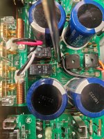
Ohh our timing must really be in sync. Thanks for responding with these two posts. Your hints from yesterday really had me grinding a lot of circuit reading and scouting on the PCB. Well If I tell you that resistors R659 and R660 measure 27K and 44K respectively would you believe this ?, I was righting to inform you about this while you were writing your last post.All the these different symbols indicate Rotel's efforts to control how ground currents flow. On page 16 PA section, note how the shells of the RCA jacks connect to the PA circuit, and the "ground break" resistor R659.
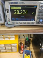
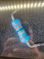
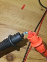
Resistors 659 and 650 are supposed to be 2.2 Ohms each. So I removed one and measures 27K. I removed the other and measures 47K. They are 5 colour band resistors, and the band colours are Red, Red, Black, Silver, Brown.
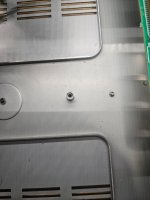
That indeed from my knowledge should be 2.2 Ohms. I double checked that with Digikey online Resistor Calculator and colours refer to 2.2 Ohms resistor. So Am immediately replacing them and feedback back to you. The mechanical Earth which is just a post and the motherboard support screw holds the board's Ground location firmly on that post. I checked that one and mechanically is ok and sound.
I also checked with DMM Digital Ground Vs Chassis Ground and that measures -2VDC. This -2VDC was becoming annoying 🙁
So wait a few minutes and I will feedback you.
Bingo....
Having replaced the two Earth Isolating Resistors R659 and R650, this cured all of the problems that were previously causing "AMP Protection". Now I can have both speaker sets on, whilst having Tone Bypass=Enable or Disable without causing further AMP Protection. So now it remains whether I can enjoy music without the infamous Relay clicking. I have placed both Grey Audio wires from the I/O Board onto the AMP Board. The -2VDC has disappeared from the speaker Posts and whilst both of these grey wire we also had "Amp Protection" if both were inserted. This issue has also disappeared.
Hooking up to listen to music....
Doors L.A Woman
Both speaker sets = Enabled.
Tone Bypass=Disabled.
IPOD Hooked up
Volume Max ===> No clicks
No AMP Protection
NO DC on Speaker Posts
No Biasing needed.
Just pure music
Attachments
Thimios Good afternoon. Yeah actually am running through the circuit diagram again trying to figure out why both and why These particular ones, could that has been from a bad XLR input ? These two resistors appeared to me that were there to create their own "Virtual Earth" or ground, which had to be -2VDC below chassis level. Thanks you for all efforts and hints. I will be checking this amp in the next few days.Good!
If those, are inp.gnd loop breakers then I'm afraid that this amplifier isn't stable.
I can't see any other reason for resistors burning.
Good!
If those, are inp.gnd loop breakers then I'm afraid that this amplifier isn't stable.
I can't see any other reason for gnd breakers burning.🤔
It's possible that a defective source device had a fault to power mains--- maybe. Then connecting to Rotel would make entire signal ground hot re safety ground and would have destroyed ground break resistors. Do you know of history before you received it?
I'm still curious about source of -2V. That's worth understanding to ensure good audio quality.
Great work!
Hi,
In my post #45 I mentioned something about the 3.3v regulator, when I found out the hard way that there are 3 or 4 different Ground positions. At that time that regulator for 3.3v It was measuring 3.29V on its output. Today I thought I'd check all voltages again. That particular regulator measures 4.14V instead of 3.3V. This means immediate replacement. The 5V one still measures ok. So no more testing until the new part arrives. Am also ordering 2.2Ohms resistors 1% tolerance to sub the ones I used to replace the faulty ones (R659 and R660). The sub ones are rated 5% tolerance. Continue measuring power from different points around the circuit +-18V +-5V and +-7V around transistor Series Transistor Shunt regulators Q911 to Q916....!
I ll keep you posted ..
Best regards
If you're going to be removing R659 and R660 anyway, troubleshooting the -2V mystery might be easier with those resistors absent.
However, the fact both resistors are open suggests that something dramatic (potentially lethal) happened in the past. The rear panel and schematics don't seem to show a 3-wire power cord. Your recent bench work hasn't revealed anything within the Rotel, but please be careful!
Best regards.
However, the fact both resistors are open suggests that something dramatic (potentially lethal) happened in the past. The rear panel and schematics don't seem to show a 3-wire power cord. Your recent bench work hasn't revealed anything within the Rotel, but please be careful!
Best regards.
Hello,
The parts arrived today, the resistors and the regulator have been replaced. It seems that the 2.2V disappeared from my measurements and. the output measurements on the speaker posts is now absolute 0V. It used to be -5mV or -2mV if you remember.
I have been trying all inputs with the Ipod directly instead of using the special USB Ipod connection, and the system heats even less that it used to be while I had the issue.
Checked all voltages from all Transistor Series shunt regulators and they seem to be 0.2v to 0.5v out, from circuit description and I think that this is not bad at all.
Bearing in mind all these I consider this issue resolved.
I would like to thank @BSST and @thimios as well as everyone who contributed helping me resolve the issue.
Until next time...! 🙂
- Home
- Amplifiers
- Solid State
- Rotel 1570 AMP in Protection mode!