Good morning BSST, thanks for coming back.Easiest is to measure with scope with signal applied, with DC coupling of scope. There should not any shift of DC component with presence of AC. Shifting DC in presence of AC may suggest a distortion mechanism.
I think I was measuring and reported wrong stuff yesterday. So I refreshed my knowledge a little bit this morning.
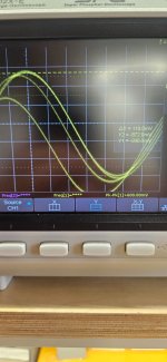
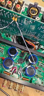
I got the same setup as yesterday on the Amplifier. It seems that the DC Offset is a bit higher than the 100mv. I used my scope
facilities and measured the offset. Its 118mV as you can see from the attached picture.
1. I am informing again that the voltage between points Emitter Resistors (Speaker connection before relays) and Chassis Ground is measuring still -1.5VDC with my DMM. Although as one can see from my pictures in one or two posts earlier I had marked on the board that the voltage there at the bus bar was -4mv and -2mv. That changed since yesterday and is now measuring -1.556Volts each channel. I don't know why.
2. Am not sure though that my DMM can compensate for that. But I will skip the Low pass filter exercise for some time later.
3. Back to our original problem:
A.) We all agree here that the amp so far does not seem to have any serious issues and that this board seems to be ok ?
Are we all aligned with this ?
B.) @MBZ:- I took measurements for the what it seems to be a uPC1723 Amp Protection IC. Are these measurements I gave you correct from your experience and knowledge ?
C.) @BSST :- In an earlier post I did mentioned that even with speakers disconnected, enabling speaker sets A and /or B relays triggered protection. That is correct and still stands for. This was the original Issue. However at one point I managed to have either of the two speaker sets selected without going into protection mode. . Then If I had selected both Speaker sets, the unit tripped. (See my initial video on this thread). This is why I needed the groups here help
D.) @BSST:- You are stating that this shouldn’t happen. You believe this behaviour presents a troubleshooting opportunity. Why does connecting this path (Which path am asking ? The one am currently using ? from the emitter Resistors and Chassis ?) that ostensibly has no loading provoke protection?
The answer if I understood correctly is : because I have installed speakers between the points indicated in the attached diagram and basically we bypassed the uPC1237 and relays do and status is, and later on MBZ suggested to measure everything around that IC cause there is a suspicion that is a fake IC based on his exposure with these. I did not get a reply whether is a fake or not.
Troubleshooting continues. PS I have asked formally for a Service manual from the Distributor here ! I doubt it but 😳
Thank you all for support. Its been a great experience.
Attachments

Short answer.
1)No input signal,d.c. voltage between RED & BLACK arrow greater than 100mV is a fault condition and relay is not activated.
2) periodically d.c presence between RED & BLACK arrow is a fault condition too, maybe oscillation.
Touching the zobel resistor,do you feel this hot 🔥?
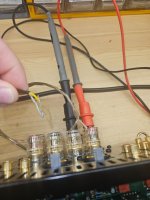
Connect the d.c voltmeter using crocodiles,read the d c voltage value,use a shorted RCA plug.
Plug in the selected input,read the d.c voltage value again.
1)No input signal,d.c. voltage between RED & BLACK arrow greater than 100mV is a fault condition and relay is not activated.
2) periodically d.c presence between RED & BLACK arrow is a fault condition too, maybe oscillation.
Touching the zobel resistor,do you feel this hot 🔥?
Connect the d.c voltmeter using crocodiles,read the d c voltage value,use a shorted RCA plug.
Plug in the selected input,read the d.c voltage value again.
Last edited:
Would you provide details about scope photo in post 61?
I agree completely with thimios. Maybe something has changed. Please measure DC out with no load applied, before speaker relays. If you find greater than 100mV DC, would you also measure voltages at bases of Q607, i.e. input base, feedback base, and output, all measurements with black lead on ground. Both channels if appropriate.
Thanks.
Hello @thimios and @BSST,
Ok Yesterday noon I took your advises and I thought may be I carry on troubleshooting and measure things around.
As I had to remove both of those grey thin wires that I believe send audio to the AMP board below, while I had the two RCA sockets shorted with the gold pin on the back, I secure the upper board as usual with foam flipped over in order to take measurements as you guys suggested.
I turned on the AMP ready to take measurements and just out of nowhere I thought I press either of the speaker set buttons. There it goes Speaker A stood on with no AMP protection. Quickly measured for voltage (AC or DC) right at the speaker posts (I did all), #No voltage AC or DC present there.#
So now went back a step....flipping back the upper board inserting one at a time the little grey audio cables back and powering up the AMP each time to see if it goes into Protection. #Amp=NO Protection#
Inserted both Audio cables from Top PCB back onto the AMP PCB. Power up the AMP #Amp=Protection#
My Plan after that troubleshooting above
A. Insert one grey audio (L) cable back to AMP Board and seated the top board back to its place. AMP still stays on. Selected Speaker Set A. #AMP=NO protection#.
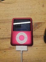
B. I run to my neighbour and borrowed his two Apple Ipods having read that it supports Ipods via the USB Port.
C. Connected left speaker wires as norm onto the Left Speaker binding posts Set A.
D. Attached Ipod in usb port at front panel, Selected USB from input selector panel. Display says Reads and indicates on Display that plays music.
Increased volume ---> Music in my ears So Lch it plays all the way from USB input ---> volume control ---> Speaker.
E. Measure voltage there at the binding posts Left channel, Music plays, Volume up, Voltage measured -2VDC, #AMP=No protection#. Some heat on Regulator and Power transistors Heatsinks anticipated (Normal and bearable). Measured for voltage at Right channel=0V basically
F. Now let me repeat this for Right channel, Speaker Set A (Writing this as I do it), Power off, lift board, remove left audio grey wire from amp board , inserted right grey wire on amp board, and flipped back top board. Connected right speaker onto the right speaker posts.
G. Powering Up, Speaker Set A on, #AMP=No Protection#. Increased volume ---> Music in my ears. So Rch it plays all the way from USB input ---> volume control ---> Speaker.
H. Measure voltage there at the binding posts Right channel, Music plays, Volume up, Voltage measured -2VDC, #AMP=No protection#. Some heat on Regulator and Power transistors Heatsinks anticipated (Normal and bearable). Measured for voltage at Left channel=0V basically
I. Trying to select Speaker set B while Set A is already selected ----> #AMP=Into protection mode#
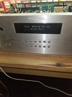
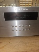
J. Reset Protection the way I found out. Disable Speaker Set A and B. Re-power on. #AMP=No protection# Select Speaker Set A. Also tried the following:- Looking around the menu, trying to find BASS and Treble. These two settings were bypassed since I bought it. Lets see if BASS and Treble works (Preamp)--> Changing from Bypass=Enable to Bypass=Disable to add bass or treble ----> #AMP=Into protection mode#
Reset the protection and am now verifying that if both grey audio wires are connected onto the amp board at same time Amp trips. Removed screws. Lifted up top board. Inserted the left grey audio wire. Both audio grey wires are now connected onto AMP board. Securing back the top board.
A. Power up again and clearing previous protection.
B. Select either Speaker Set A or Speaker Set B caused #AMP=Protection mode#
So protection modes are caused
1=When both Grey audio cables are inserted onto AMP PCB
2=Changing Tone BYPASS=ENABLE to BYPASS=DISABLE
3=Select Speaker set B while Set A is already selected, or vice versa
in the mean time resetting everything back out of protection and continue listening to some more music (Thimios point if I hear any clicks and slams). Only one channel but never mind for now ! Removed right grey audio cable from AMP board. Powered on ok No protection listening to Bob Marley (Zion)....
Low volume no distortion. Let it stabilize and increase volume ---VDC on binding posts left=-2VDC (Negative)
Previously on Right I think was 2VDC(Positive)---Checking.......! Nope its also -2VDC (Negative)
[It must have been the 100th time removing top PCB today 🙂]
All measurements carried above are with 8 Ohm speakers connected, powered up, NO Protection, USB playing, and directly at speaker Binding posts using DMM VDC polarity Black DMM to black Post and Red DMM to Red Post
Switching Speaker Set A off. Switch Speaker Set B ON. (Same as above but no load at Speakers) and measure VDC=-2VDC (Negative no load on B terminals Right Channel)
Left Channel Speaker Set B (No load) Measured VDC=-5mv (basically 0V DC) directly at speaker Binding posts using DMM VDC polarity Black DMM to black Post and Red DMM to Red Post.
Also every time I switch on the amp after resetting the Protection, I can hear DC knocking on speaker(s) immediately when speaker Relay(s) come on, Pending on which side ( L or R) the grey audio cable is connected onto the amp.
Just verifying another issue. Removing both grey audio cables from amp board and trying to listen for DC knock on speakers..
Removed both Grey audio wires from AMP Board---Powering Up---> No protection ----> Speaker SET A (Load on posts) plays music no DC Knock on speakers --> Hmmm !!! Measure VDC On binding posts since Speaker Set A is on stable ---3mvDC and -2.8mVDC left and right output posts (basically 0VDC)
So there is a presence of -2VDC on output speaker posts when the grey wires are connected onto the AMP Board ? (it does not matter left or right)
But I wanna listen to some music louder than before just to see if clicks and distortions are heard So putting back on Left Channel. .All good listening Bruno Mars Left channel Set A.. !
### Some clicking noise but not from Speakers or music. From the top Board...listening in...###
WOW---one of the red relays clicks as music plays but music is not interrupted.....
I will record that and send you video... WOW first time anticipating a relay clicking with the music rhythm.
These relays are working on 24 vdc and are driven by digital transistors. So some AC (Audio) signal is interfering with the 24VDC that drives the relays here and it makes it oscillate in rhythm with the music especially when bass is present (Like when Bob Marley music is on) ???. Looking on the 1070 Schematic as a reference to see if 24v present and trying to figure out if similar to 1570 !
Ok Guys hit me with your thoughts or experiences. !!
Ok Yesterday noon I took your advises and I thought may be I carry on troubleshooting and measure things around.
As I had to remove both of those grey thin wires that I believe send audio to the AMP board below, while I had the two RCA sockets shorted with the gold pin on the back, I secure the upper board as usual with foam flipped over in order to take measurements as you guys suggested.
I turned on the AMP ready to take measurements and just out of nowhere I thought I press either of the speaker set buttons. There it goes Speaker A stood on with no AMP protection. Quickly measured for voltage (AC or DC) right at the speaker posts (I did all), #No voltage AC or DC present there.#
So now went back a step....flipping back the upper board inserting one at a time the little grey audio cables back and powering up the AMP each time to see if it goes into Protection. #Amp=NO Protection#
Inserted both Audio cables from Top PCB back onto the AMP PCB. Power up the AMP #Amp=Protection#
My Plan after that troubleshooting above
A. Insert one grey audio (L) cable back to AMP Board and seated the top board back to its place. AMP still stays on. Selected Speaker Set A. #AMP=NO protection#.
B. I run to my neighbour and borrowed his two Apple Ipods having read that it supports Ipods via the USB Port.
C. Connected left speaker wires as norm onto the Left Speaker binding posts Set A.
D. Attached Ipod in usb port at front panel, Selected USB from input selector panel. Display says Reads and indicates on Display that plays music.
Increased volume ---> Music in my ears So Lch it plays all the way from USB input ---> volume control ---> Speaker.
E. Measure voltage there at the binding posts Left channel, Music plays, Volume up, Voltage measured -2VDC, #AMP=No protection#. Some heat on Regulator and Power transistors Heatsinks anticipated (Normal and bearable). Measured for voltage at Right channel=0V basically
F. Now let me repeat this for Right channel, Speaker Set A (Writing this as I do it), Power off, lift board, remove left audio grey wire from amp board , inserted right grey wire on amp board, and flipped back top board. Connected right speaker onto the right speaker posts.
G. Powering Up, Speaker Set A on, #AMP=No Protection#. Increased volume ---> Music in my ears. So Rch it plays all the way from USB input ---> volume control ---> Speaker.
H. Measure voltage there at the binding posts Right channel, Music plays, Volume up, Voltage measured -2VDC, #AMP=No protection#. Some heat on Regulator and Power transistors Heatsinks anticipated (Normal and bearable). Measured for voltage at Left channel=0V basically
I. Trying to select Speaker set B while Set A is already selected ----> #AMP=Into protection mode#
J. Reset Protection the way I found out. Disable Speaker Set A and B. Re-power on. #AMP=No protection# Select Speaker Set A. Also tried the following:- Looking around the menu, trying to find BASS and Treble. These two settings were bypassed since I bought it. Lets see if BASS and Treble works (Preamp)--> Changing from Bypass=Enable to Bypass=Disable to add bass or treble ----> #AMP=Into protection mode#
Reset the protection and am now verifying that if both grey audio wires are connected onto the amp board at same time Amp trips. Removed screws. Lifted up top board. Inserted the left grey audio wire. Both audio grey wires are now connected onto AMP board. Securing back the top board.
A. Power up again and clearing previous protection.
B. Select either Speaker Set A or Speaker Set B caused #AMP=Protection mode#
So protection modes are caused
1=When both Grey audio cables are inserted onto AMP PCB
2=Changing Tone BYPASS=ENABLE to BYPASS=DISABLE
3=Select Speaker set B while Set A is already selected, or vice versa
in the mean time resetting everything back out of protection and continue listening to some more music (Thimios point if I hear any clicks and slams). Only one channel but never mind for now ! Removed right grey audio cable from AMP board. Powered on ok No protection listening to Bob Marley (Zion)....
Low volume no distortion. Let it stabilize and increase volume ---VDC on binding posts left=-2VDC (Negative)
Previously on Right I think was 2VDC(Positive)---Checking.......! Nope its also -2VDC (Negative)
[It must have been the 100th time removing top PCB today 🙂]
All measurements carried above are with 8 Ohm speakers connected, powered up, NO Protection, USB playing, and directly at speaker Binding posts using DMM VDC polarity Black DMM to black Post and Red DMM to Red Post
Switching Speaker Set A off. Switch Speaker Set B ON. (Same as above but no load at Speakers) and measure VDC=-2VDC (Negative no load on B terminals Right Channel)
Left Channel Speaker Set B (No load) Measured VDC=-5mv (basically 0V DC) directly at speaker Binding posts using DMM VDC polarity Black DMM to black Post and Red DMM to Red Post.
Also every time I switch on the amp after resetting the Protection, I can hear DC knocking on speaker(s) immediately when speaker Relay(s) come on, Pending on which side ( L or R) the grey audio cable is connected onto the amp.
Just verifying another issue. Removing both grey audio cables from amp board and trying to listen for DC knock on speakers..
Removed both Grey audio wires from AMP Board---Powering Up---> No protection ----> Speaker SET A (Load on posts) plays music no DC Knock on speakers --> Hmmm !!! Measure VDC On binding posts since Speaker Set A is on stable ---3mvDC and -2.8mVDC left and right output posts (basically 0VDC)
So there is a presence of -2VDC on output speaker posts when the grey wires are connected onto the AMP Board ? (it does not matter left or right)
But I wanna listen to some music louder than before just to see if clicks and distortions are heard So putting back on Left Channel. .All good listening Bruno Mars Left channel Set A.. !
### Some clicking noise but not from Speakers or music. From the top Board...listening in...###
WOW---one of the red relays clicks as music plays but music is not interrupted.....
I will record that and send you video... WOW first time anticipating a relay clicking with the music rhythm.
These relays are working on 24 vdc and are driven by digital transistors. So some AC (Audio) signal is interfering with the 24VDC that drives the relays here and it makes it oscillate in rhythm with the music especially when bass is present (Like when Bob Marley music is on) ???. Looking on the 1070 Schematic as a reference to see if 24v present and trying to figure out if similar to 1570 !
Ok Guys hit me with your thoughts or experiences. !!
Attachments

Good morning ThimiosShort answer.
1)No input signal,d.c. voltage between RED & BLACK arrow greater than 100mV is a fault condition and relay is not activated.
2) periodically d.c presence between RED & BLACK arrow is a fault condition too, maybe oscillation.
Touching the zobel resistor,do you feel this hot 🔥?
Connect the d.c voltmeter using crocodiles,read the d c voltage value,use a shorted RCA plug.
Plug in the selected input,read the d.c voltage value again.
I though I answer to all these you ask:-
1. When no Input signal is present at Amplifier inputs (i.e grey audio cables removed from Amp Board) I get -3 to -5mVDC basically 0V on binding speaker posts (Set A or Set B) or at RED and BLACK arrow points
2. DC Presence is on the RED and BLACK arrows only when Input signal is present at AMP Input.
Touching the Zobel Resistor is warm (both) normal temp because room temp and current passing through when speakers are attached on binding posts
3. I believe I have answered part of your query in 2 throughout my post #64. However I will do the part with the shorted RCA at CD Input having removed USB IPOD input, measuring VDC at speaker posts Right Channel.
Here it is
======
1. Shorted RCA and set it at Rear CD Input, Right channel.
2. Set DMM leads in Speaker output posts Crocodile clips
3. Select AMP input CD,
4. Speaker Cables on Binding posts (Load on)
5. Voltage measured is -2VDC
6. Removed Speaker Cables from Binding Posts (Load Off)
7. Voltage measured is again -2VDC
For me its clear that when either of the two (or both) grey audio cables are connected from the top board onto the amp board there is -2VDC present on speaker binding posts, whether or not there are speaker(s) connected on the posts.
Thank you and let me know !
Attachments

Good progress!
I may be blind. Would you explain which "grey audio cables" you are mentioning? Can you identify them in the service manual to help me locate them?
-2VDC on both speaker channels?
Your demo had music on right channel only, as adding left tripped protection. What if you had music on left speaker and right disconnected--- same result?
If SM corresponds to your unit, the clicking relay is RY408 and is associated with Tape 2 input. Is this correct? Can you follow coil switching activity with your scope as music playing? Stable supply voltage to top of coil? Follow coil drive waveforms to Q416 and Q408. Stable supply to emitter of Q408? Any clues on base of Q408, etc?

Good morning there..I agree completely with thimios. Maybe something has changed. Please measure DC out with no load applied, before speaker relays. If you find greater than 100mV DC, would you also measure voltages at bases of Q607, i.e. input base, feedback base, and output, all measurements with black lead on ground. Both channels if appropriate.
Please view my latest posts #64 and #65 for some of your thoughts I've answered. So with load or without load on speakers now output is -2VDC. That voltage is present on speaker binding posts not because of the load but because I apply the grey audio wire from the top board onto the amplifier board.
You are referring to Q607 on the RA-1070 Schematic ? I think on the RA1570 all these transistors have now being replaced with NE5532 OP Amps. Both of these amps in all of their pins they measure -2VDC except their power pins which measure -16 and +16 VDC in respect to chassis.
Attachments
If have music on left and right disconnected I will have, and had music on Left. When both of these audio carrying grey wires are attached on Amp board below device tripsYour demo had music on right channel only, as adding left tripped protection. What if you had music on left speaker and right disconnected--- same result?
Please review my video in post #52. The short wires.I may be blind. Would you explain which "grey audio cables" you are mentioning? Can you identify them in the service manual to help me locate them?
It seems stable but not 24VDC. Its 26VDC. The rest you are mentioning I have to investigate as of tomorrow and feedback you.Stable supply voltage to top of coil? Follow coil drive waveforms to Q416 and Q408. Stable supply to emitter of Q408? Any clues on base of Q408, etc?
Hi karatzdi,
Several miscellaneous comments:
The grey audio cables are still a bit mysterious. I can't play any of the mp4 files in posts 5 and 52, so I'm blocked from what they would show me. Do other members have similar experience? Other mp4 files play fine. The Doors music with the clicking relay is promising. Viewed with your scope, are the relay waveforms purely "digital" switching, or are there "analog" signals riding atop the switching control lines? Seems like coupling via power supplies, but that's a very wild guess.
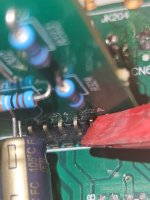
In post 42, there's a solder joint that looks devoid of solder: picture 7/10, right edge of the photo, just above center.
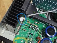
Are you pointing to a 5532 opamp in post 67, second photo?
Post 64 seems like a gold mine. Are the grey audio cables analogous to the K1A cable connecting the PA input, page 7 of 8 in the service manual? With cable disconnected, would you would you confirm the "ground" lead of the cable is in fact at 0V re other ground points? Is there any DC present between the cable ground and the signal wire? Any variation when you exercise the tone control bypass option? And of course, same questions for both channels?
You mention all signal pins of the 5532 opamp show -2VDC. That seems very odd. What do they measure with grey cables removed vs. connected?
Good luck!
Several miscellaneous comments:
The grey audio cables are still a bit mysterious. I can't play any of the mp4 files in posts 5 and 52, so I'm blocked from what they would show me. Do other members have similar experience? Other mp4 files play fine. The Doors music with the clicking relay is promising. Viewed with your scope, are the relay waveforms purely "digital" switching, or are there "analog" signals riding atop the switching control lines? Seems like coupling via power supplies, but that's a very wild guess.
In post 42, there's a solder joint that looks devoid of solder: picture 7/10, right edge of the photo, just above center.
Are you pointing to a 5532 opamp in post 67, second photo?
Post 64 seems like a gold mine. Are the grey audio cables analogous to the K1A cable connecting the PA input, page 7 of 8 in the service manual? With cable disconnected, would you would you confirm the "ground" lead of the cable is in fact at 0V re other ground points? Is there any DC present between the cable ground and the signal wire? Any variation when you exercise the tone control bypass option? And of course, same questions for both channels?
You mention all signal pins of the 5532 opamp show -2VDC. That seems very odd. What do they measure with grey cables removed vs. connected?
Good luck!
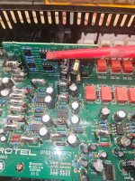
I have attached 2 pictures, showing those grey Audio cables that originate from the I/O Board onto the amplifier Board. They also show (Circled) where these attach on the AMP Board.The grey audio cables are still a bit mysterious. I can't play any of the mp4 files in posts 5 and 52, so I'm blocked from what they would show me.
I did not know that you could not play the video or some of my videos. On the video #52 I was just explaining that these grey wires are short in length and cant really insert audio through the I/O Board as it is impossible to have the board flipped back and take measurements at the same time. The I/O board sits on top of the AMP Board, covering it thus not allowing one to take measurements. The same video explains also that Am attaching speaker wires, describing on which side, I will be attaching the resistors to take measurements before the relays. I guess we progressed after that 🙂
Yes I am pointing at a 5532 over there !Are you pointing to a 5532 opamp in post 67, second photo?
To test this am going to use a 0.1uF cap with my Oscilloscope and trace at the + and - power pins on that specific relay.The Doors music with the clicking relay is promising. Viewed with your scope, are the relay waveforms purely "digital" switching, or are there "analog" signals riding atop the switching control lines? Seems like coupling via power supplies, but that's a very wild guess.
...Testing....! Yes !!!! I have audio (Analog) there whilst the music plays !!! on both pins of the relay (either + or -)
Ohh gosh !!. Just saw it my self. I need to reassemble the whole thing again.. I will do it but at a bit later stage.In post 42, there's a solder joint that looks devoid of solder: picture 7/10, right edge of the photo, just above center.
Attachments
Good sleuthing to find that relay! Maybe discovering how audio finds its way onto relay coils will lead to the culprit.
BTW, I did attempt to ask about a SM via inquiry at a Rotel portal. It led to a dealer/service shop (I think) who never responded. I did not pursue phone calls.
BTW, I did attempt to ask about a SM via inquiry at a Rotel portal. It led to a dealer/service shop (I think) who never responded. I did not pursue phone calls.
Continue replying from your previous post...!Post 64 seems like a gold mine. Are the grey audio cables analogous to the K1A cable connecting the PA input, page 7 of 8 in the service manual? With cable disconnected, would you would you confirm the "ground" lead of the cable is in fact at 0V re other ground points? Is there any DC present between the cable ground and the signal wire? Any variation when you exercise the tone control bypass option? And of course, same questions for both channels?
Am not sure if these cables are analogous to the K1A connecting the PA input page 7 of 8 you are referring to. Do you have a service manual for RA1570 ? because you are referring specifically. Am basing my circuit readings to see if there is a match somewhere on the RA1070, but things are way different.
Describing here the Grey Wire.:-
The Grey wire has a Ground core which I suppose is "ground" and a White coloured core that carries the audio.
With the Grey Audio wire disconnected from the AMP board (Left or Right channel), DMM Black wire to ground and, Red wire onto the ground core of that grey wire DMM reads -2VDC.
Also DMM Black to ground and Red to the White Core DMM reads -2VDC (What the @@#$%%!! ? is going on here).
DMM Between White-core and ground-core of the Grey wire DMM reads -0VDC Yes there is - in front of the reading.
Both IC's NE5532 read the same values -2VDC whether or not the Grey wires are connected or disconnected from AMPYou mention all signal pins of the 5532 opamp show -2VDC. That seems very odd. What do they measure with grey cables removed vs. connected?
Good sleuthing to find that relay! Maybe discovering how audio finds its way onto relay coils will lead to the culprit.
BTW, I did attempt to ask about a SM via inquiry at a Rotel portal. It led to a dealer/service shop (I think) who never responded. I did not pursue phone calls.
Yeah basically I thought to pump up the volume in an attempt to satisfy Thimios request if any clicks are heard from the speakers. Instead I heard clicks coming from a Miniature relay 🙂
Thanks for asking though, cause I also chase it from here and no replies. Is it difficult ? Can you pursue though call backs or you feel they are not going to do it ?
So to recoup :-
AMP still trip under 3 conditions
1=When both Grey audio cables are inserted onto AMP PCB
2=Changing Tone BYPASS=ENABLE to BYPASS=DISABLE
3=Select Speaker set B while Set A is already selected, or vice versa
I have managed to set music and checked both speaker paths (L and R) with Music. Plays nicely but only one channel is allowed to be connected to amp from I/O Board. If both connected -->Condition 1 occurs as above
When music plays and one Grey wire is connected onto AMP Board that channel which is connected at that time, reads -2VDC on the respective Speaker Posts.
When music is playing I set speaker switch to OFF and increase volume to max. Where music peaks one relay (identified as RY408) its coil oscillates (Clicks with music peaks on and off)
BSST and myself tend to believe that audio is bleeding into some DC Supply line.
Also there is a board that reads 016-X1672B05 which features 2 NE5532 OP Amps. All of their pins read -2VDC except pins 4 and 8 which are the power pins and read +- 16V. Sporadically if I try to read the +16v pin the AMP trips again. But the later is well understood as to why.
In the mean time still looking for RA1570 Manual or even the RA1572MKII will do as some pics I saw the layout and prob the circuits are the same.
If anyone in this forum can help finding the manual I will appreciate it. In the mean time Thanks to BSST who reached out to Rotel.
Rotel used to be great about sharing their service manuals. Have they gone thru a change in ownership recently? I lost track of who owns them.
I used their contact form and did get a reply:
Thanks for your email and query. I am sorry but we are not allowed to publish the sensitive schematics as they are part of the brands intellectual property and all marked as Confidential. But if there was some question you had about the design we could ask the engineers if they have any comments. Also, if your unit needs repair you can ask a service center to send an email from their business address to sales@rotel.com and they can review to see if technical documents could be provided.
My latest attempt has been frustrating. I called the only phone number offered, was dierected via selection menu to a support department. Eventually a voice meeage came instructed me to use web site to make inquiry.
I got automated reply, but no follow up so far. I went down this path in an earlier attempt. It was a black hole—- no further actively.
I got automated reply, but no follow up so far. I went down this path in an earlier attempt. It was a black hole—- no further actively.
- Home
- Amplifiers
- Solid State
- Rotel 1570 AMP in Protection mode!