Not a lot of info on the EMT , all China links are dead end. It does not look to be pin compatible with the uPC.@ostripper: Is there a known difference between EMT1237B and uPC1237 ?
Thanks
Shame it is SIPxxx , they could of sold more as a direct replacement.
OS
My suspicion is that the EMT1237B is an adapter that converts a uPC1237 from an 8 pin SIP format to a 8 pin mini-dip format. Has your exploration confirmed that?
If we can establish with certainty it's uPC1237, we can analyze voltages with more confidence.
If we can establish with certainty it's uPC1237, we can analyze voltages with more confidence.
My memory failed me again--- I thought I recalled a Mini-DIP version of the uPC1237, but couldn't find anything similar.
I still think it might be helpful to see the component side of the adapter board, but I'm inclined to assume it'a a uPC1237 or an equivalent. Would you tabulate the voltages at the 8 pins of the module in an excel file as in post 10 ? I assume pin 1 is indicated by silkscreen artwork.
Thanks!
I still think it might be helpful to see the component side of the adapter board, but I'm inclined to assume it'a a uPC1237 or an equivalent. Would you tabulate the voltages at the 8 pins of the module in an excel file as in post 10 ? I assume pin 1 is indicated by silkscreen artwork.
Thanks!
The few existing links describe a 8-pin SIP. But , a different "superior" design.
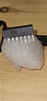
The dip-8 adaptor seems to have a 8-pin SIP on it (photo). The small adaptor PCB Has EMT-xxxx
An adaptor for the described EMT1237B , which is NOT a uPC.
Such a nice FR-4 amp PCB , It just takes a few semi's to make a decent DC-OC circuit . Why did
Rotel choose a freakin' proprietary "orphan" ?
Need the SM !!
Scrutinize the first photo in post 14. I can imagine the pins of an 8-pin mini-dip near the pins for the 8 pin SIP socket.
I speculate that the adapter is fabricated from ordinary generic parts--- maybe an LM393. Point being, maybe it's possible to repair the module and restore functionality. Hence, the request for a close-up picture of the hidden parts on the module.
Of course it's possible the problem lies in the motherboard but, lacking a schematic, we have to to learn enough to sleuth out the problem.
Last edited:
BSST good morning. You are correct its an 8pin Slip SIP and its been converted to a 8 pin DIP. Then sits nicely on AMP PCB. Nothing else exist on that conversion SIP to DIP but the 1237IC.
However new things are up
On the top PCB there are two Regulators. One 7805A (5v Regulator) and one BA33BC0T (3.3v Regulator)
both in a TO-220FP-3 case. So measuring the voltages in and out always with respect to ground:
5v Regulator in: 9.8V
5v Regulator out: 3.06v
===============
3.3v Regulator in: 9.8V
3.3v Regulator out: 1.9v. Notice this :- Play around with the speaker set buttons voltage changes to 2.4v
I have removed and checked on my bench the 3.3v regulator with a bench power supply
In:9v out 4.3 v. However inducing a load of 4.7 ohms across its output voltage drops to 1.9v drawing around 690mA (should have drawn 0.91A)
I have done the same on the 7805 regulator with 4.7 ohms and output is stable at 5v and draws 1.06A
I have replaced the 3.3v regulator with an LM 1086 but previously I have benched it with the 4.7ohms and output is constant at 3.3v 0.91A. Made wiring re-arrangements because the I/O pins are not in the same order and powered it up. Same problem Hitting both speaker buttons AMP goes in protect mode.
Something is not right that's why the logic keeps tripping the whole amp. Like you said ...We need a SM. Can I order one from USA ?
I already put the assy back on the PCB. Got a picture of the replaced IC, in case was the problemIt sure would be good to have a schematic...
Can you remove that EMT1237B "chip" and post a close-up photo of its component side?
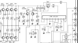
Hi mbz I found this circuit diagram of a ROTEL RA1070 utilizing a uPC1237. I cut a portion just to compare it with the RA1570.Example from a Yamaha RX-V3900, over current sensing transistor circled in red, only included to give you some idea.
I don't think I can. Its a bit impossible, however some of the voltage indicated on this circuit diagram are also measured on the actual uPC1237 on the PCB Pin 4=2.4vDC, Pin8=3.4vDC, Pin7=2.2vDC.
Attachments
The schematic is encouraging. Are you able to measure voltages of the uPC1237 in your unit. Saw your pins noted above. What about pins 1 & 2 ?
I'm attempting to inquire of Rotel about SM. They may ask about serial number. Should I proceed? Guidance?
I'm attempting to inquire of Rotel about SM. They may ask about serial number. Should I proceed? Guidance?
I will measure tomorrow and let you know about pins 1 and 2The schematic is encouraging. Are you able to measure voltages of the uPC1237 in your unit. Saw your pins noted above. What about pins 1 & 2 ?
Serial no of the device is 702-5431111. Kindly let me know of the cost for the manual if any
Appreciate
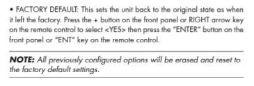
Hello. Yes I did a factory default as it is stated in the manual. Attached capture ! Unfortunately that did not work. ! But hey thanks!Did you ever try a reset of the amp?
Attachments

Hello Thimios.As soon as you have measured for d.c presence already,if I'm you,I have to connect a cheap speaker in position of multimeter and play some music.😉
To be more in the safe side,add an electrolytic cap.in series with speaker.1000uf,2200uf whatever you have stock.
Back in my bench, trying to apply what you posted.
1. I used my Signal Gen and through an RCA plug applied 400mv of 1KHz sine audio wave at CD Input
2. I attached two speakers on Speaker set A.
3. Turned on AMP and SG. Momentarily as soon as the Speaker Relay was switched on, the AMP tripped and went into "Amp protection". Be aware that I have not been fast enough to select the appropriate Input, the amp tripped immediately into AMP Protection.
4. Now needs to have both Speaker sets to off in order to stay on and carry on troubleshooting.
5. I did not set an electrolytic in Series, instead I choose to go directly on speakers
6. My speakers seem to be fine still. 😉
Strange, very strange behaviour. No DC present at outputs when was selecting speaker set A or B previously.
May be no voltage present until a load is inserted on outputs...Maybe !
Did anyone lads ask for a service manual ? Nothing here !
I believe that you have misunderstood my advice.
I speak for a speaker connection between gnd and coil.
P.S sorry just now I see that coil is after relay.
You need to connect the test speaker between gnd and amplifier's out before relay .Use an electrolytic in series as explained.
Keep input low,400mv is a large signal!
I speak for a speaker connection between gnd and coil.
P.S sorry just now I see that coil is after relay.
You need to connect the test speaker between gnd and amplifier's out before relay .Use an electrolytic in series as explained.
Keep input low,400mv is a large signal!
Last edited:
You need to connect the test speaker between gnd and amplifier's out before relay .Use an electrolytic in series as explained.
Keep input low,400mv is a large signal!
Ok will try that and feedback tomorrow. So you are trying to see if there's an amplified signal just before protection ? Yes ?
Keep input low,400mv is a large signal!
Ok will try that and feedback tomorrow. So you are trying to see if there's an amplified signal just before protection ? Yes ?
Ok !Keep input low,400mv is a large signal!
Signal generator is useful as soon as you will use a scope connected to the output.
I would prefer another source playing music.
This way anything wrong like crackling, distorted e.t.c will be clearly audible.
I would prefer another source playing music.
This way anything wrong like crackling, distorted e.t.c will be clearly audible.
That will most probably be the implementation in your unit.I found this circuit diagram of a ROTEL RA1070 utilizing a uPC1237.
Need Vdc at each of your pins so we can make an assessment on whether your IC is a cloned uPC1237. Pin 1 and 2 are of most interest. A good GND pin is also needed.
In post 26 you were describing trouble with 5V and 3.3V regulators. Did you get that issue resolved to your satisfaction?
BTW, I've been using a copy of Rotel RA1070 service manual as a stand-in for the desired RA1570 manual. Thanks for the work-around. I hope it corresponds well with your amp.
In comment 4, you indicate you have to switch off both A and B speakers to avoid tripping protection. If you disconnected the speakers, would you be able to activate both A and B relays without triggering protection? The schematic shows nothing but wiring between the relays and the speaker posts, so I would expect this test to work. And if you are able to produce amp output signal without incurring protection, this suggests that protection is provoked by current flow rather than voltage offset error.
In the spreadsheet data in post 10, were the emitter voltages measured before the relay? They look fine, but they are without load. Can you connect speakers and avoid protection if you keep volume at 0? Examining pins 1 and 2 of the protection IC seems key. I'm guessing pin 2 may look ok, but a problem will be found on pin 1.
BTW, I've been using a copy of Rotel RA1070 service manual as a stand-in for the desired RA1570 manual. Thanks for the work-around. I hope it corresponds well with your amp.
Some questions about this post.Hello Thimios.
Back in my bench, trying to apply what you posted.
1. I used my Signal Gen and through an RCA plug applied 400mv of 1KHz sine audio wave at CD Input
2. I attached two speakers on Speaker set A.
3. Turned on AMP and SG. Momentarily as soon as the Speaker Relay was switched on, the AMP tripped and went into "Amp protection". Be aware that I have not been fast enough to select the appropriate Input, the amp tripped immediately into AMP Protection.
4. Now needs to have both Speaker sets to off in order to stay on and carry on troubleshooting.
5. I did not set an electrolytic in Series, instead I choose to go directly on speakers
6. My speakers seem to be fine still. 😉
Strange, very strange behaviour. No DC present at outputs when was selecting speaker set A or B previously.
May be no voltage present until a load is inserted on outputs...Maybe !
Did anyone lads ask for a service manual ? Nothing here !
In comment 4, you indicate you have to switch off both A and B speakers to avoid tripping protection. If you disconnected the speakers, would you be able to activate both A and B relays without triggering protection? The schematic shows nothing but wiring between the relays and the speaker posts, so I would expect this test to work. And if you are able to produce amp output signal without incurring protection, this suggests that protection is provoked by current flow rather than voltage offset error.
In the spreadsheet data in post 10, were the emitter voltages measured before the relay? They look fine, but they are without load. Can you connect speakers and avoid protection if you keep volume at 0? Examining pins 1 and 2 of the protection IC seems key. I'm guessing pin 2 may look ok, but a problem will be found on pin 1.
- Home
- Amplifiers
- Solid State
- Rotel 1570 AMP in Protection mode!