Thanks Mihai! I will try it. The bass control is incredible. Everything else is in its place. Doesn't seem to matter how complex the recording is everything can still be heard. And even more amazing is total lack of fatigue even at quite high levels for a long time.
Please watch the temperature of the transistors. Those silicon pads often conduct heath worse than mica + goop.
Yes !!!!
I ran out of rubbery type and used mica on one the devices in another amp.
The currents in the devices measured as very different, from a matched set I had measured up.
I instantly doubted my matching.
It turns out that the mica mounted device was running cooler than the adjacent sil-pad mounted devices.
That cooler Tj resulted in higher Vbe and less current. The sil pad devices now had to take a bigger share of the current and ran hotter still.
Changing the other two devices to mica, cured the mismatched currents. The other polarity remained as sil-pad mounted for the duration of my testing.
Last edited:
Paul, if you like, I will assist you with the build of a nice case for your FC-100.
The FC-100 is worth giving the nicest-looking case to it!
It is the very best DIY-amplifier that I have ever listened to!
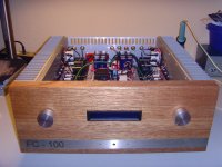
This is how I did it (see attached image).
I you like my case's "general" design: you need a couple of small ALU-brackets, three 2mm thick ALU-plates (top, bottom and rear) and a wooden front plate.
Since I have integrated my passive PRE into the FC-100's case "on the second floor" (making it an Integrated Amplifier), I needed to install a LCD into the wooden plate.
I should have done the insertion of the LCD into the wooden front in a better way, I know. The black plastic frame really looks nasty!
Best regards - Rudi
P.S. The "silver" knobs and intarsia do "not look good" either. I would have done the front in another way today!
The FC-100 is worth giving the nicest-looking case to it!
It is the very best DIY-amplifier that I have ever listened to!
This is how I did it (see attached image).
I you like my case's "general" design: you need a couple of small ALU-brackets, three 2mm thick ALU-plates (top, bottom and rear) and a wooden front plate.
Since I have integrated my passive PRE into the FC-100's case "on the second floor" (making it an Integrated Amplifier), I needed to install a LCD into the wooden plate.
I should have done the insertion of the LCD into the wooden front in a better way, I know. The black plastic frame really looks nasty!
Best regards - Rudi
P.S. The "silver" knobs and intarsia do "not look good" either. I would have done the front in another way today!
Attachments
Last edited:
Does anybody known of a suitable point to add a line level sub woofer output without any sonic impact? I know this would normally be done in the preamplifier but I am using Rudi"s passive VCpre and don't want to load it up. Maybe The NFB point could be used?
Paul, if you are afraid of "overloading" the LDRs of the VCPre, I will send you a line-buffer PCB, my modified version of Calvin's buffer, a very, very splendid buffer - for nothing 🙂 !
Best regards - Rudi
Many thanks for that offer. I am sure it is a great buffer. But I am trying to keep the signal chain as short and simple as possible.
At the moment its just DAC/CD -> VCPRE -> FC100 and it sounds sublime.
Does anybody known of a suitable point to add a line level sub woofer output without any sonic impact? I know this would normally be done in the preamplifier but I am using Rudi"s passive VCpre and don't want to load it up. Maybe The NFB point could be used?
Just use a voltage divider and take it from the output.
Sheldon
Just use a voltage divider and take it from the output.
Sheldon
Thanks Sheldon I may well do that.
so now I will add in three more solder joints and two more resistors by adoptingI am trying to keep the signal chain as short and simple as possible.
At the moment its just DAC/CD -> VCPRE -> FC100 and it sounds sublime.
use a voltage divider
so now I will add in three more solder joints and two more resistors by adopting
??
It's about as simple as one can get, will have no effect on the amp output (which is a voltage source), and need only one channel, as sub frequencies are not usually channel separated in the mix anyway. Many powered subs have both line and power options for inputs. The output impedance needn't be low to the sub. And it's simple to try.
Sheldon
He is refusing to adopt normal Line Level equipment because it adds "extras" to his unusable existing assembly.
Why should be then substitute some other "extra" when he has already rejected everything that might interfere with his perfect but unusable system?
Why should be then substitute some other "extra" when he has already rejected everything that might interfere with his perfect but unusable system?
Point taken. Your suggestion is what I'd do. But it requires more care to get it right and some circuit and chassis modification to the pre. There's a wide range of experience and comfort level with mods on this forum. Functionally, dividing the power amp output does give a line level output, but requires no internal or chassis mods. It doesn't preclude modding the pre in the future.
Sheldon
Sheldon
Hi,
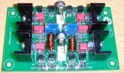
I want to use bigger Caps in the PSU - is it necessary to recalculate the 0R1 (..better Inductance) of this Pi-Filter ? Im not very used to this equations. A hint would be nice 🙂
thx
I want to use bigger Caps in the PSU - is it necessary to recalculate the 0R1 (..better Inductance) of this Pi-Filter ? Im not very used to this equations. A hint would be nice 🙂
thx
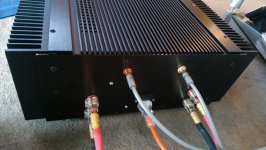
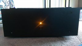
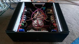
Almost finished putting one of my FC-100s into a case. Still need to tidy up internal wiring
Beautiful case work! Where did you source the top plate?
Regarding the internal wiring, I would move the input lines away from the transformers as far as possible.
Sorry I have to reask my question with a bit more information's. I wrote inductance because in Rudis BuildersManual there is although a version with some wire wound arround the resistor. A plain Resistor is no CLC network. So im sorry for the strange question.
....the org question
Hi,
I want to use bigger Caps in the PSU - is it necessary to recalculate the 0R1 (..better Inductance) of this Pi-Filter ? Im not very used to this equations. A hint would be nice 🙂
thx
....the org question
Hi,
I want to use bigger Caps in the PSU - is it necessary to recalculate the 0R1 (..better Inductance) of this Pi-Filter ? Im not very used to this equations. A hint would be nice 🙂
thx
Last edited:
Beautiful case work! Where did you source the top plate?
Regarding the internal wiring, I would move the input lines away from the transformers as far as possible.
Thanks Pooge! It is an ebay case. Quite expensive but the FC-100 deserves it I think. I had to "supersize" it a bit with bushes as I am using Conrad heatsinks and mounting plates. I do hope to tidy up the internal wiring when I get a chance. It is hard to stop listening though!
See : New 2014 Full Aluminum Class A Amplifier Chassis Preamp Enclosure 400 150 373mm | eBay
Last edited:
- Status
- Not open for further replies.
- Home
- Amplifiers
- Solid State
- Roender's FC-100 prototype and builder's thread