Doesn't this amp use 160v rail caps? 210v will destroy them. It probably has a defective regulator.
The attached diagram should be close enough for the parts you asked about. Confirm by comparing other components in the area.
The attached diagram should be close enough for the parts you asked about. Confirm by comparing other components in the area.
Attachments
Yes Perry, this amplifier uses 160v rail caps.
I'm going to check the regulators ...
I have also noticed that R35 and R36 are hot, quickly ...
Thank you very much for the scheme, Perry !!! I will be of great help!
I'm going to check the regulators ...
I have also noticed that R35 and R36 are hot, quickly ...
Thank you very much for the scheme, Perry !!! I will be of great help!
The resistors are overheating due to the high voltage.
To clarify, the regulators that I referred to are on the power supply schematic, sections B-D8. Q36 and the components connected to it regulate the voltage from the low-voltage supply like the older amps. Get that circuit working. It's the simplest.
To clarify, the regulators that I referred to are on the power supply schematic, sections B-D8. Q36 and the components connected to it regulate the voltage from the low-voltage supply like the older amps. Get that circuit working. It's the simplest.
Attachments
Okay, I've extracted Q36, I checked it, and it looks good, anyway, I replaced it with a new one, I checked all that zone, and I did not find any components in bad condition, I checked tensions, and the only voltage which is a bit high is the TP4 on the pin of R102, which gives me 30V ...
And according to scheme must be 21V...
And according to scheme must be 21V...
Remove D11. Does the rail voltage drop?
If not, post the DC voltage on all pins of the 3526 (with D11 removed).
If not, post the DC voltage on all pins of the 3526 (with D11 removed).
OK. For Rockford BD amps, you have to measure across the rail caps (red and blue wires in this amp).
The voltage is safe for now. After you get the audio stage working and the amp connected to the power supply, you can reinstall D1 and confirm that the voltage is safe.
The voltage is safe for now. After you get the audio stage working and the amp connected to the power supply, you can reinstall D1 and confirm that the voltage is safe.
To help protect the output stage, you can insert a current limiting resistor with the red or blue wires. I use a 4 ohm but anything between 2 and 10 ohms should allow the amp to function well enough for testing.
Ok, Perry.
I need to know :
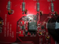
In this amplifier, the configuration of the LM5110 gate controller is inverting, or not inverting?
I need to know :
In this amplifier, the configuration of the LM5110 gate controller is inverting, or not inverting?
In the photos I have of a similar amp, the IC has a 1M suffix which means that both halves are non-inverting. I don't have anything on the t40001bd specifically.
I received today the parts I ordered (the 20 fet, and 5 LM5110 not inverted)
I have done some inquiries before installing the fet ...
I connected the amplifier to observe voltages in each of the four fet groups of the audio output motherboard, and I detected differences ...
In the first set (Q404, 405, 410, 430, 434)
Source: 0v
Drain: 145v
Gate: 6,6v
In the second group (Q431, 414, 413, 412, 411)
Source: 4v
Drain: 0v
Gate: 6v
In the third group (Q433, 429, 428, 427, 426)
Source: 4v
Drain: 0v
Gate: 9.7v
In the fourth group (Q432, 420, 419, 418, 417)
Source: 0v
Drain: 145v
Gate: 3,2v
At all gate of the fets, I see square waveform except in the fourth group.
is this correct?
Yes, Perry, there is square waveform on the output pins of the two IC's.
I have seen the voltages and in U202 on the output pins there are 3.6v, and on U204 there are 1.3v....
I have seen the voltages and in U202 on the output pins there are 3.6v, and on U204 there are 1.3v....
Are the supply voltages the same for both ICs?
Is the amplitude the same on the output for both ICs?
I'm assuming that you're measuring the voltages you're posting with a multimeter.
Is the amplitude the same on the output for both ICs?
I'm assuming that you're measuring the voltages you're posting with a multimeter.
- Status
- Not open for further replies.
- Home
- General Interest
- Car Audio
- rockford fosgate t40001bd