Red probe on center leg of CR1004.
Black probe on the center leg of CR1005.
In Rockford BD amps, there is no reference to ground for the rails. They float.
Please (and this applies to anyone who needs repair help) use your sig line to list all equipment you have, editing it as equipment changes. Include the model numbers.
Top of page, menu USER CP >> EDIT SIGNATURE
Oscilloscope (yes or no)
Multimeter(s)
Type of signal source (grounded RCA shields preferred).
Soldering iron
Desoldering pump
Power supply
2 ohm current limiting resistor (hollow cylindrical ceramic 100w preferred)
Hi Perry,
Voltage measured at center leg of CR1004/CR1005 is 102V. This stayed steady before the oscillations starts and is the same voltage during oscillations as well. It basically didn't change at all until the amp turned off into protect.
I changed the TL072C opamp and it didn't change anything. I noticed measuring pin 7 (vcc) of the opamp, it doesn't have any voltage? But the amp will still turn on and work?
I am picking up another one of these amps today, so I will have a reference point to compare..
You need to use circuit board designations when referring to the components. Which TL072 are you referring to?
Are the large capacitors in the center of the amp loose?
Is R9 near the rectifiers broken on one terminal?
You have to realize that not many people know the number and quantity of every component in any amp. Having the circuit board designations saves a lot of time.
Is R9 near the rectifiers broken on one terminal?
You have to realize that not many people know the number and quantity of every component in any amp. Having the circuit board designations saves a lot of time.
R9 resistor is not broken. The large caps the one closest to the RCAs was loose. I reflowed the connection and it is solid again. I will add some rtv to them later.
The new amp I got when it is powered on it draws about 5amps at 13v and has 88V across the 2 diodes cr1004/1005
The non working amp will only draw about 1.5 amps at 13v when it does turn on and has 102v across the diodes.
With just gnd and remote connected, I'll see gate drive for a couple seconds upon power up and then it'll disappear and protect light will come on.
I'd remove the caps and check them for value. They often break away inside and rattle if you shake them.
If the capacitors are open, that could account for the difference.
Start a new thread with a different title for the second amp.
If the capacitors are open, that could account for the difference.
Start a new thread with a different title for the second amp.
Would the caps affect the gate drive disappearing?
The other amp is a working amp and nothing wrong with it. I am using it as a reference
The other amp is a working amp and nothing wrong with it. I am using it as a reference
Excessive noise could possibly cause problems.
If you can use your scope in differential mode, see if the rails are noisy (1 probe each on the center legs of the rectifiers).
If you have a large 100v cap, you could connect it across the rail caps to see if it makes a difference.
If you can use your scope in differential mode, see if the rails are noisy (1 probe each on the center legs of the rectifiers).
If you have a large 100v cap, you could connect it across the rail caps to see if it makes a difference.
Right, but at the moment the gate drive is disappearing even without the FETs switching. Only remote is connected when i test.
Goodmorning everyone.
I want to bring back to you my experience with a rockford t600-2 (same series as this t1500) I had problems with the audio section (one of the two channels made a frying-like noise, but worked).
I tried to swap the two driver boards, but the defect was always on the same channel.
After wasting time, head and sleep, I put the board against a strong light and realized that it hides other tracks in a central layer, so I came to the conclusion that these power series amplifiers from that year of construction have PCBs wth 3 or 4 layers (which is why they are so compact).
I have never been able to understand the problem where it was, also because if Rockford does not release the schematics, we cannot know how they are made.
It may be that you lose the oscillator signal and if you move the board, it reappears, because there will be some hidden track that is not working well, but you will never know, or at least you will lose your soul to find it.
Is it building rail voltage when you power up the amp (even if it goes into protect)?
Yes, when it first turns on and gate drive is present, it will attempt to build rail voltage. Since I have the driver board connected via jumper wires right now, I removed the 2 wires going to the PS FETs to cancel out switching noises but it still disappears in the same fashion. I noticed that even with the 2 PWM wires disconnected, when I apply B+ the gate drive will disappear right away. If I leave it on REMOTE and GND only, it will stay on sometimes longer before disappearing.
Today I will try powering the driver board with no other connections to it asides from power to try and isolate what is causing the drive signals to stop.
Goodmorning everyone.
I want to bring back to you my experience with a rockford t600-2 (same series as this t1500) I had problems with the audio section (one of the two channels made a frying-like noise, but worked).
I tried to swap the two driver boards, but the defect was always on the same channel.
After wasting time, head and sleep, I put the board against a strong light and realized that it hides other tracks in a central layer, so I came to the conclusion that these power series amplifiers from that year of construction have PCBs wth 3 or 4 layers (which is why they are so compact).
I have never been able to understand the problem where it was, also because if Rockford does not release the schematics, we cannot know how they are made.
It may be that you lose the oscillator signal and if you move the board, it reappears, because there will be some hidden track that is not working well, but you will never know, or at least you will lose your soul to find it.
Thank you for your feedback. At one point it did seem like moving the board around or pushing on certain components would cause the drive to re-appear.
What's strange is the board will be sitting completely still when gate drive disappears, I'll power cycle and gate drive will immediately come back.
I removed the drive board from the amp and powered it by itself. Gate drive doesn't disappear anymore but it is sometimes jittery.
At first it was drawing about 60mA, i come back an hour later and it is now drawing about 45mA, but still has gate drive. It appears that the duty cycle is a bit lower as well.. Power cycle and it looks normal again, but still jittery.
C106 sets the frequency of the PWM, I replaced it with another 2.2nF cap but doesn't seem to have helped.
With the drive board running standalone like this, the duty should be consistent and not change right?
Without being in the main board, some of the components for the regulator may be missing.
Is pin 1 pulled up by a resistor and pin 2 pulled down by a resistor?
Is pin 1 pulled up by a resistor and pin 2 pulled down by a resistor?
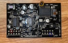
I didn't pull anything up or down and only had 12V connected to red circle and GND connected to blue circle (attached pic).
It seems that when the drive board is wired to the amp, something is causing the comparators to trigger. Do you know what could cause a fault with only REMOTE power?
It seems that when the drive board is wired to the amp, something is causing the comparators to trigger. Do you know what could cause a fault with only REMOTE power?
Attachments
I was referring to the pins of the 3526, as you were in the previous post.
As far as I know, the comparators only affect the 3526 through the SD terminal. Is that pin being driven as to shut down the IC?
As far as I know, the comparators only affect the 3526 through the SD terminal. Is that pin being driven as to shut down the IC?
Hmm.. I didn't remove the actual IC, but am powering the BD power board as shown in the image above. Sorry if that was a little confusing.
The Shutdown pin of the 3526 does go LOW when the BD power board is installed in the amp. Which means something is driving one (or more) of the comparators outputs to a faulted state when it is wired to the amp. What could potentially trigger the comparators when only REMOTE power is applied?
The Shutdown pin of the 3526 does go LOW when the BD power board is installed in the amp. Which means something is driving one (or more) of the comparators outputs to a faulted state when it is wired to the amp. What could potentially trigger the comparators when only REMOTE power is applied?
With the board out of the amp, is anything affecting the SD pin of the IC? If not, that's not a concern with the instability of the output of the IC at this point.
Did you check to see if pins 1 and 2 of the 3526 have pull-up and pull-down resistors?
Did you check to see if pins 1 and 2 of the 3526 have pull-up and pull-down resistors?
- Home
- General Interest
- Car Audio
- Rockford Fosgate T1500-1BDCP - No Gate Drive