Regulator inputs are generally pulled to the 5v reference output and ground.
Pin 2 needs to be pulled down to ground to eliminate it as an issue.
Pin 2 needs to be pulled down to ground to eliminate it as an issue.
Grounding pin 2 seems to have helped a bit.
The gate drive looks pretty solid now. I wired the BD drive board back to the amp and the gate drive will still disappear after a second upon REMOTE power.
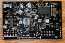
I found out that by disconnecting the connection in purple (see attached) that gate drive will no longer disappear and I can power up the amp fine. Rails are at 88V steady and gate drive looks good as well.
What is this connection measuring? DC offset measurement at the speaker terminals is 17mV. Temperature probes on the output/power side measure ~3k, 7k respectively iirc.
The gate drive looks pretty solid now. I wired the BD drive board back to the amp and the gate drive will still disappear after a second upon REMOTE power.
I found out that by disconnecting the connection in purple (see attached) that gate drive will no longer disappear and I can power up the amp fine. Rails are at 88V steady and gate drive looks good as well.
What is this connection measuring? DC offset measurement at the speaker terminals is 17mV. Temperature probes on the output/power side measure ~3k, 7k respectively iirc.
Attachments
If you added a pulldown resistor to pin 2 of the 3526, that was only for testing with the driver board out of the circuit.
If no one has the diagrams for this amp, you may have to see if it's close enough to something like the T10001bd to understand the circuit. Use a PDF reader that will allow you to mark up the diagram to put the circuit board designations from your amp onto the components of the T10001.
If no one has the diagrams for this amp, you may have to see if it's close enough to something like the T10001bd to understand the circuit. Use a PDF reader that will allow you to mark up the diagram to put the circuit board designations from your amp onto the components of the T10001.