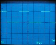
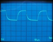
When you load the FET location, you look at the curve produced by the drive circuit and make sure it's pulling up and down as expected. The first image below is an unloaded drive signal and even though it looks OK, it may not be if the driver components are working 100% as they should. Loading it changes the signal to what you see in the second image. You can see that it's changed but it's being pulled up and down. If it had a bad drive component (most commonly a bad PNP driver transistor), the signal wouldn't go down nearly as far as it does in the photo.
Attachments
that scope is at workshop, i dont have current limit on input power, only battery power. 2amp fuse inline maybe?
found Crazylogix007 on youtube and he said these rf amps doesnt like output transistors with N on its part number, have you heard this?
This automotive tester/scope is useless measuring these things. Im thinking something id wrong. Q219 pins 11.6v, - 1.3v, 27.4.
Q215 - 28.8v, - 1.3v - 28.8v.
Q115 - 28.8v, - 1.3v, - 28.8v.
Q119 11.6v, 1.3v, 27.4v
Q215 - 28.8v, - 1.3v - 28.8v.
Q115 - 28.8v, - 1.3v, - 28.8v.
Q119 11.6v, 1.3v, 27.4v
Last edited:
If the output FETs are out of the circuit, that doesn't look unexpected. Why do you think that shows a problem?
yes no outputs on board, put them in and give it a go? scope - wire was connected battery negative, is that right place? i tried to measure irf3205, it kinda looked like your second picture but wasnt that clean, havent use this type of "scope"
Last edited:
Without seeing the waveform, I can't comment on it.
Install the outputs for the previously good channel and confirm that it's still OK, then install the ones in the other channel. Set the bias pots fully counter-clockwise before powering the amp with the outputs.
If you don't have a current limiter for the 12v supply, insert an ATO/ATC 5 amp fuse in the B+ line before applying power.
there is -28v dc on right channel. q215 has 14volts on G. others has 27-28.
amp idles 0.54amps without bias.
all new outputs on board
amp idles 0.54amps without bias.
all new outputs on board
Last edited:
-28v using the main ground or measuring the voltage across the speaker terminals with the meter probes on the speaker terminals as marked (+/-)?
sorry. its positive 28v.
oh shie, i really have to run between 2 places to get this done
oh shie, i really have to run between 2 places to get this done
Last edited:
Use the main/primary ground. Is it positive?
Are you sure you have the N and P-channel FETs in the correct location?
Are you sure you have the N and P-channel FETs in the correct location?
yes, readings correct now. i can measure few components looked from schematics Q219 Q215 legs, so should not be soldering problem?
- Home
- General Interest
- Car Audio
- Rockford Fosgate 160A2 doesnt power up