Well, I have new results
I connected the potentiometer U17 as indicated in Seankane thread, I have also removed R31 and R35
No MOSFET transistor output on the motherboard
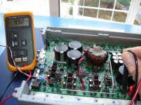
When connecting, and testing, the pins on the motherboard of the first group of eight MOSFETs, -9.70v. and 9.68 v. respectively when turning the knob from right to left.
But, to do the same with the other group of eight MOSFETs, and turn the knob, -9.92 v only appear as shown in photo
Which makes me suspect that there is any fault in what belongs to that section, but where? Any hints?
I will order more parts ... (LM6171, HCPL2211, MIC4420, etc. ...)
I connected the potentiometer U17 as indicated in Seankane thread, I have also removed R31 and R35
No MOSFET transistor output on the motherboard
When connecting, and testing, the pins on the motherboard of the first group of eight MOSFETs, -9.70v. and 9.68 v. respectively when turning the knob from right to left.
But, to do the same with the other group of eight MOSFETs, and turn the knob, -9.92 v only appear as shown in photo
Which makes me suspect that there is any fault in what belongs to that section, but where? Any hints?
I will order more parts ... (LM6171, HCPL2211, MIC4420, etc. ...)
Attachments
You need to check the input and output of each previous component (driver IC, opto-coupler, op-amps) to see where the input and output don't change together as you turn the pot.
Well, I'm here again
I have checked, U5, U6, U7, U8, U9, U10 and U15,
Turning the potentiometer all well regulated, volts positive and negative volt, at its inputs and its outputs, except the output of U15 (pin 7) and the output of U6 (pin 5) to give - 9.70 v always
I'm surprised that the latter are wrong, I have changed recently, is it possible that you are wrong? IC should I check some more? (TL 074, LM6172IM, .....)
Hey, Perry, what do you think? the gould or the hameg?
http://www.ebay.es/itm/180864467380?ssPageName=STRK:MEWAX:IT&_trksid=p3984.m1423.l2649
http://www.ebay.es/itm/120897679647?ssPageName=STRK:MEWAX:IT&_trksid=p3984.m1423.l2649
http://www.ebay.es/itm/180864467380?ssPageName=STRK:MEWAX:IT&_trksid=p3984.m1423.l2649
http://www.ebay.es/itm/120897679647?ssPageName=STRK:MEWAX:IT&_trksid=p3984.m1423.l2649
Sorry that I didn't see #103 earlier.
Confirm that the voltage measured directly across pins 2 and 3 of U15 are switching from 1.1v to -0.6v when you go from one extreme to the other with the potentiometer.
If that's right and the output of the opto-coupler isn't swinging to plus and minus 9v, the opto-coupler is defective. I'm assuming that the opto-coupler has approximately 18v across pins 5 and 8.
The scope with the sine wave locked on the display seems less likely to be defective. The one with only two straight traces could have several problems. Either one would should be good enough they are both in good working order.
Perry quiet, do not feel, I know I'm patient and wait
I've done the checks that have told me and the voltage measured directly across pins 2 and 3 of the U15 is changing from 1.4V up to -0.68 V when going from one extreme to another with a potentiometer.
Between pins 5 and 8 is 19V
And on pin 7, there is always -9.70 V, while moving from one extreme to another with potentiometer
So I'll order a HCPL2211 (I heard that this IC, it is delicate to handle, is it true?)
Regarding the scope, most likely, I do, is to follow his wise advice, and try to stay with the Gould Ø300
Thanks again, Perry, and when you receive the parts, tell what happens.
Well, I got the A2211 (U15)
And, check voltages, I noticed that when you turn the potentiometer back and forth in the output of this IC, I have, -9.70 v and 7.28v is this correct?
For a comparison with the other IC (U9) I have, -9.90 v and 10.28v Do these tensions should be more similar (7.28 and 10.28)?
¿I can ride MEHSA strip with all the mosfet?
Don't install the FETs yet.
Measure the DC voltage on U15 with the black probe on pin 5 and the red probe on pin 8. Post that voltage.
Measure the voltage on pin 7 (black probe on pin 5 again).
Post the DC voltage on pin 7 with the pot clockwise and counterclockwise.
Measure the DC voltage on U15 with the black probe on pin 5 and the red probe on pin 8. Post that voltage.
Measure the voltage on pin 7 (black probe on pin 5 again).
Post the DC voltage on pin 7 with the pot clockwise and counterclockwise.
U15 probe pin8 red and black probe on pin 5: 19.68 v
pin7 (black probe pin5): 0.2 v
DC pin7 right: 7.31 v
DC pin7 left: -9.69 V (with the black probe to negative)
I have also checked U9
DC pin7 right: -10.89 v and swinging ..
DC pin7 left: 7.01 v and down ...
pin7 (black probe pin5): 0.2 v
DC pin7 right: 7.31 v
DC pin7 left: -9.69 V (with the black probe to negative)
I have also checked U9
DC pin7 right: -10.89 v and swinging ..
DC pin7 left: 7.01 v and down ...
For this don't use ground as a reference. Post the voltage (black on 5, red on 7) with the pot clockwise and counterclockwise.
Well, black test probe, in pin5, and red pin7:
Potentiometer to the right, 17.16 v
And potentiometer to the left, 0.20 v.
Potentiometer to the right, 17.16 v
And potentiometer to the left, 0.20 v.
Now go back and make sure that all outputs are swinging to positive and negative 9v (black probe on leg 3 and red probe on leg 1).
Well, I'm back in the measurements,
In the first eight MOSFET (Q102, 103, 12, etc) 9.75 V and -9.81 V
In the following eight (Q104, 105,106, 8, etc) -9.92 V and 9.76 V
Perry, do you think the amplifier is ready for you solder the mosfet sixteen?
In the first eight MOSFET (Q102, 103, 12, etc) 9.75 V and -9.81 V
In the following eight (Q104, 105,106, 8, etc) -9.92 V and 9.76 V
Perry, do you think the amplifier is ready for you solder the mosfet sixteen?
Okay, I'm glad to hear that
The scope, almost,, almost,, I'm about to get it, give me a week and I think I will ....
Wait to have it, to continue with this repair.
Once you have it, I hope to send a photo, with the waveform.
The scope, almost,, almost,, I'm about to get it, give me a week and I think I will ....
Wait to have it, to continue with this repair.
Once you have it, I hope to send a photo, with the waveform.
When you send a photo of the waveforms, you'll need to connect the 3rd leg of Q103 to the speaker ground terminal. Post photos of the signal on the gate legs of Q103 and Q106.Set the scope to display 3-4 full cycles (timebase set to 5-10us) and the vertical amp set to 5v/div.
Well, Perry, this afternoon I will pick up the oscilloscope, which has already arrived.
All that tells me to do, to publish the wave,,,,,
Already I can remove the pot, and re-solder the resistors?
and you then do what you say and publish the waveform, right?
All that tells me to do, to publish the wave,,,,,
Already I can remove the pot, and re-solder the resistors?
and you then do what you say and publish the waveform, right?
Yes, you'll have to remove the pot to allow it to produce a square wave. You can also reinstall all resistors. Leave the output transistors out of the circuit.
If you don't know how to use an oscilloscope, read page 73 of the site.
If you don't know how to use an oscilloscope, read page 73 of the site.
The output transistors .... is that, yet I have not ...
I can do the measuring, without them?
Okay, I will read page 73
I can do the measuring, without them?
Okay, I will read page 73
- Status
- Not open for further replies.
- Home
- General Interest
- Car Audio
- Rockford Fosgate 1501bd preview Repairing