Do you have a rail-rail square wave on the output transistors?
If you don't have a scope, post the DC voltage on all pins of U17.
If you don't have a scope, post the DC voltage on all pins of U17.
I remember ... yesterday, checking voltages at different points, there was only high voltage, in a group of eight MOSFET (the 3415), in the other group, there was no high voltage (the 6215) this may be significant?
Anyway, this afternoon will send voltage U17 (now I'm at work)
Perry is being a great help for this repair.
Anyway, this afternoon will send voltage U17 (now I'm at work)
Perry is being a great help for this repair.
U17
pin 1: 0
pin 2: 0
pin 3: 0
pin 4: -9,90
pin 5: 0
pin 6: -2,76
pin 7: 9,80
pin 8: 0
too U6
pin 1: -9,70
pin 2 and 4: -9,90
pin 3: 9,70
pin 5: -9,90
look good, right?
pin 1: 0
pin 2: 0
pin 3: 0
pin 4: -9,90
pin 5: 0
pin 6: -2,76
pin 7: 9,80
pin 8: 0
too U6
pin 1: -9,70
pin 2 and 4: -9,90
pin 3: 9,70
pin 5: -9,90
look good, right?
Post the voltage for this IC again but this time, place the black probe on pin 2 or 4. Be very careful not to allow the probe to short to the heatsink on the IC.
Do the same for the other driver IC.
Do the same for the other driver IC.
U5
pin 1: 0
pin 2: -1,21
pin 3: 0,08
pin 4: -9,83
pin 5: 0
pin 6: 1,92
pin 7: 9,86
pin 8: 0
U8
pin 1: 0
pin 2: 8,14
pin 3: 0,17
pin 4: -9,84
pin 5: 0
pin 6: -8,23
pin 7: 9,85
pin 8: 0
pin 1: 0
pin 2: -1,21
pin 3: 0,08
pin 4: -9,83
pin 5: 0
pin 6: 1,92
pin 7: 9,86
pin 8: 0
U8
pin 1: 0
pin 2: 8,14
pin 3: 0,17
pin 4: -9,84
pin 5: 0
pin 6: -8,23
pin 7: 9,85
pin 8: 0
Okay, I'll replace it, I think I have, this afternoon when you do, tell what happens, again, thanks Perry.
I ... I think I've had bad luck again ...
I'll divide this post into two parts: before the explosion and after the explosion.
prior to the explosion:
I replaced U7, and new tensions that gave me were:
Pin 1: 0
Pin 2: 0.035
Pin 3: 0.035
pin 4: -9.89
pin 5: 0
pin 6: 5.86
pin 7: 9.89
pin 8: 0
Do these tensions were correct, or there was still something wrong?
When connecting the speaker produced a bit of pink noise (sssshhhhs and 0.5 V at the terminals) but I had to remove it soon, because I saw some smoke out around R180 or R181 (not sure, but next came there )
I disconnected the speaker and I started to check voltages, for example, I saw that tensions had risen U5 (pin 2: -5.09 and pin 6: 8.26) also in U17 (pin 6: -5.75)
The explosion:
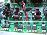
When I was checking U8 (pin 2: 5.77) and touching the pin 3, not sure if I have a short between pin2 and pin 3 with the probe (I have inspected the probe and the IC pins and no trace of the spark), the case is, who have exploited Q12 and Q109 (see picture of how they have been)
Do not know what could have happened, I unsoldered the group of eight mosfet, and found six in short, in its three terminals!
What do you think Perry?
I'll start from scratch, and I will order more parts ...
Again, I again thank you for your help, Perry
The day I get repair this amp, I'll open a bottle of champagne ...
I'll divide this post into two parts: before the explosion and after the explosion.
prior to the explosion:
I replaced U7, and new tensions that gave me were:
Pin 1: 0
Pin 2: 0.035
Pin 3: 0.035
pin 4: -9.89
pin 5: 0
pin 6: 5.86
pin 7: 9.89
pin 8: 0
Do these tensions were correct, or there was still something wrong?
When connecting the speaker produced a bit of pink noise (sssshhhhs and 0.5 V at the terminals) but I had to remove it soon, because I saw some smoke out around R180 or R181 (not sure, but next came there )
I disconnected the speaker and I started to check voltages, for example, I saw that tensions had risen U5 (pin 2: -5.09 and pin 6: 8.26) also in U17 (pin 6: -5.75)
The explosion:
When I was checking U8 (pin 2: 5.77) and touching the pin 3, not sure if I have a short between pin2 and pin 3 with the probe (I have inspected the probe and the IC pins and no trace of the spark), the case is, who have exploited Q12 and Q109 (see picture of how they have been)
Do not know what could have happened, I unsoldered the group of eight mosfet, and found six in short, in its three terminals!
What do you think Perry?
I'll start from scratch, and I will order more parts ...
Again, I again thank you for your help, Perry
The day I get repair this amp, I'll open a bottle of champagne ...
Attachments
The voltages on U7 were better.
Desolder and remove the other 8 FETs from the board (don't desolder them from the MEHSA insulator).
Do you have a spare potentiometer (4.7k ohms to 100k ohms will work)?
Desolder and remove the other 8 FETs from the board (don't desolder them from the MEHSA insulator).
Do you have a spare potentiometer (4.7k ohms to 100k ohms will work)?
A potentiometer 4.7 k, or 100k? What value?
Do you mean? tell me the value and buy it tomorrow ...
Do you mean? tell me the value and buy it tomorrow ...
Buy a 10k potentiometer, preferably one that you can hold easily (not too small) and with a shaft that you can turn with your fingers.
Well, I have the 10k pot, and I removed all of the output MOSFET.
Now, do you want to solder the pins on the potentiometer pins 2, 4 and 7 of U17?
Now, do you want to solder the pins on the potentiometer pins 2, 4 and 7 of U17?
- Status
- Not open for further replies.
- Home
- General Interest
- Car Audio
- Rockford Fosgate 1501bd preview Repairing