Hi, i have this old 1996 fosgate 100x2 amp This amp was working good when I stored it away and now only one channel works. I tested the speaker output and got 32.4v on the right channel? I check alll the output transistor and the 1 ohm resistor on both side. They check out okay. The left channel is fine and plays music fine. Nothing was burn. What am i missing here. I would like to say thanks to those of you that help me before. Thanks to Perry for all the help and time. I know he's busy i appreciate Perry your time.
An externally hosted image should be here but it was not working when we last tested it.
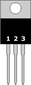
If you're absolutely sure that none of the output transistors is shorted, give me the DC voltage on each FET in the defective channel with the amp powered up (no audio). Place the black probe in leg 3 of the FET being tested and the red probe on leg 1 and then leg 2. For each transistor, post the circuit board designation.
Q#
Leg 1:
Leg 2:
Q#
Leg 1:
Leg 2:
Q#
Leg 1:
Leg 2:
Q#
Leg 1:
Leg 2:
Q#
Leg 1:
Leg 2:
Q#
Leg 1:
Leg 2:
Q#
Leg 1:
Leg 2:
Q#
Leg 1:
Leg 2:
Q#225
Leg 1: 65.3v
Leg 2: .261v
Q#215
Leg 1: 65.3v
Leg 2: .261v
Q#219
Leg 1: 0v
Leg 2: -17.66v
Q#224
Leg 1: 0v
Leg 2: -17.66v
Leg 1: 65.3v
Leg 2: .261v
Q#215
Leg 1: 65.3v
Leg 2: .261v
Q#219
Leg 1: 0v
Leg 2: -17.66v
Q#224
Leg 1: 0v
Leg 2: -17.66v
Last edited:
Did you have the black probe on the 3rd leg of each transistor being tested?
What are the circuit board designations for each of the transistors?
What are the circuit board designations for each of the transistors?
Yes i just add the negative on the 17.66v. I start on the bottom left of the amp in the picture that i posted. The reading should be down to up.

With your meter on ohms, do you read infinite resistance from leg 1 to the other legs of the FETs you removed?
Try it again but this time, place the black probe on chassis ground.
Q225
Leg 1:
Leg 2:
Leg 3:
Q215
Leg1:
Leg 2:
Leg 3:
Q219
Leg1:
Leg 2:
Leg 3:
Q224
Leg1:
Leg 2:
Leg 3:
Are there any burned SMD resistors near the bias pot? The ones marked 200 are the ones you need to check. Are they within tolerance?
Q225
Leg 1:
Leg 2:
Leg 3:
Q215
Leg1:
Leg 2:
Leg 3:
Q219
Leg1:
Leg 2:
Leg 3:
Q224
Leg1:
Leg 2:
Leg 3:
Are there any burned SMD resistors near the bias pot? The ones marked 200 are the ones you need to check. Are they within tolerance?
Q225
Leg 1: -32.7
Leg 2: 32.47
Leg 3: -32.29v
Q215
Leg1: -32.7v
Leg 2: 32.47v
Leg 3: -32.29v
Q219
Leg1: 32.47v
Leg 2: 32.47v
Leg 3: 14.79v
Q224
Leg1: 32.47v
Leg 2: 32.47v
Leg 3: 14.79 v
Leg 1: -32.7
Leg 2: 32.47
Leg 3: -32.29v
Q215
Leg1: -32.7v
Leg 2: 32.47v
Leg 3: -32.29v
Q219
Leg1: 32.47v
Leg 2: 32.47v
Leg 3: 14.79v
Q224
Leg1: 32.47v
Leg 2: 32.47v
Leg 3: 14.79 v
Sorry i had them in the wrong place, but i have them like it would be on the amp.
Q225
Leg 3: -32.29
Leg 2: 32.47
Leg 1: -32.7v
Q215
Leg 3: -32.29v
Leg 2: 32.47v
Leg 1: -32.7v
Q219
Leg 3: 32.47v
Leg 2: 32.47v
Leg 1: 14.79v
Q224
Leg 3: 32.47v
Leg 2: 32.47v
Leg 1: 14.79 v
Q225
Leg 3: -32.29
Leg 2: 32.47
Leg 1: -32.7v
Q215
Leg 3: -32.29v
Leg 2: 32.47v
Leg 1: -32.7v
Q219
Leg 3: 32.47v
Leg 2: 32.47v
Leg 1: 14.79v
Q224
Leg 3: 32.47v
Leg 2: 32.47v
Leg 1: 14.79 v
I don't know where the transistor is but it's likely near the bias pot.
I don't know if it's the same as the ix. I have the x2 schematic. Email me if you want it.
babin_perry@yahoo.com
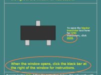
Go to the following page and click the circled link. Read the circled text also. Send me the screen cap for Q221.
Basic Amplifier Repair - Transistor Test Applet Link
I don't know if it's the same as the ix. I have the x2 schematic. Email me if you want it.
babin_perry@yahoo.com
Go to the following page and click the circled link. Read the circled text also. Send me the screen cap for Q221.
Basic Amplifier Repair - Transistor Test Applet Link
Attachments
- Status
- Not open for further replies.
- Home
- General Interest
- Car Audio
- Rockford Fosgate 100x2