Find R133 and check it.
Are you saying that the silkscreen on your amp was unreadable?
R133 = 0V
No, I was speaking of the drawing you posted. The silkscreen is fine.
Isn't the photo I posted essentially identical to your amp?
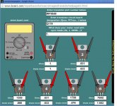
Q112 should have near rail voltage on its collector. With no voltage across R133, it would appear that that channel is missing the positive rail voltage or there is a broken solder connection.
Q112 should have near rail voltage on its collector. With no voltage across R133, it would appear that that channel is missing the positive rail voltage or there is a broken solder connection.
Is that large piece in the center of the photo the bias pot? If so, it does look very similar to the 301s.
I just rechecked R133 and I have 19.6V I'm not sure what happened the first time. Perhaps a probe wasn't making good contact? Looking at your photo, Q112 shows 21.52, 1.005, 0.482. My Q112 is all very consistent at 11.29, 11.97, 11.26. That has me concerned.
I just rechecked R133 and I have 19.6V I'm not sure what happened the first time. Perhaps a probe wasn't making good contact? Looking at your photo, Q112 shows 21.52, 1.005, 0.482. My Q112 is all very consistent at 11.29, 11.97, 11.26. That has me concerned.
With 20v across it, it should have been nearly hot enough to desolder itself.
Solder it back into the board and see if anything has changed.
Solder it back into the board and see if anything has changed.
Is Q112 shorted? Compare resistance to corresponding resistor in other channel. If it appears to be defective, remove it and check out of the board.
R233 = 622 ohms
Q112 does not appear shorted. Diode check mode. Red on leg 1 (looking at the flat side of the FET) Black on 2= .995V Red on 1, Black on 3 .823V
Q112 does not appear shorted. Diode check mode. Red on leg 1 (looking at the flat side of the FET) Black on 2= .995V Red on 1, Black on 3 .823V
Q212 1.896 and .821 Quite a bit different on the the first check. Pretty much the same on the second.
Should I solder Q107 and 116 back in or, leave them out for now?
Should I remove Q112?
Should I solder Q107 and 116 back in or, leave them out for now?
Should I remove Q112?
Last edited:
leave them out.
I just realized that the the voltage across R133 is essentially the drive voltage for the 9540 output. With the rails near 30v and the gate 20v down, that channel should have full positive rail voltage at the speaker terminal unless there is a bad connection or a defective component for the following parts:
R136
Q119
R150
If you cannot find the problem, post the DC voltage on all of those parts with the black probe on ground.
As a side note, I have problems reading long strings of numbers so reading through all of the numbers you posted would be nearly impossible without taking it and reformatting it. You don't need to do anything with it. In the future, post them vertically.
Black probe on ground during voltage measurements.
R136 = 30.8VDC I remember we measured those at around .1 ohms some time back.
R150 = 11.28VDC 10.2 ohms
Q119 = 11.28VDC
Question on the ohm tests with high ohms. The value I recorded started there and continued rising. What is happening that is causing the resistance to just keep climbing?
R136 = 30.8VDC I remember we measured those at around .1 ohms some time back.
R150 = 11.28VDC 10.2 ohms
Q119 = 11.28VDC
Question on the ohm tests with high ohms. The value I recorded started there and continued rising. What is happening that is causing the resistance to just keep climbing?
Attachments
Q119 needs voltages on all 3 terminals.
Q119 11.2, 30.8, 30.8 VDC
This channel should have full rail on the speaker terminal. Did I get the channels confused somewhere? I thought the right channel had the DC.
- Status
- Not open for further replies.
- Home
- General Interest
- Car Audio
- Rockford 301s Won't power up