Muffled and crackling.
http://vid82.photobucket.com/albums/j262/Rocguy/Amp repair/IMG_0692_zpsxhxa46vo.mp4
It sounds loud on the computer. It wasn't that loud in the truck
http://vid82.photobucket.com/albums/j262/Rocguy/Amp repair/IMG_0692_zpsxhxa46vo.mp4
It sounds loud on the computer. It wasn't that loud in the truck
I don't watch videos.
Didn't you state that the bias for each channel increased the idle current?
Didn't you state that the bias for each channel increased the idle current?
You had me turn the bias all the way back down and, said we can worry about it later.
If I made that statement, it was through your test instructions. What I recall is after the initial power up, the light would no longer illuminate. You said it was due to the inrush current charging the capacitors. I did notice when I inserted the meter inline yesterday, the light came on. I measured 2.5 to 2.8A
If I made that statement, it was through your test instructions. What I recall is after the initial power up, the light would no longer illuminate. You said it was due to the inrush current charging the capacitors. I did notice when I inserted the meter inline yesterday, the light came on. I measured 2.5 to 2.8A
At some point, didn't you turn the bias pots up but not enough to make the light brighter, then later turned them more so that the light did get brighter?
Inserting the amp meter should not have caused the current to increase.
Inserting the amp meter should not have caused the current to increase.
Yes, I just looked back and in post 143, it did begin to illuminate. I had forgotten that.
I thought it was interesting the light came on simply by inserting the meter but, I didn't think too deeply about it.
I thought it was interesting the light came on simply by inserting the meter but, I didn't think too deeply about it.
Remove the meter if it's causing an increase in current draw.
With the speaker connected to the left channel, operate all switches and pots through their entire range to see if the audio clears up.
With the speaker connected to the left channel, operate all switches and pots through their entire range to see if the audio clears up.
Look at the area around where you made the various solder connections. Do you see any bad connections or solder bridges?
Are you sure that you installed the IRF540 and 9540 in the correct locations?
Are you sure that you installed the IRF540 and 9540 in the correct locations?
Look at the area around where you made the various solder connections. Do you see any bad connections or solder bridges?
Are you sure that you installed the IRF540 and 9540 in the correct locations?
Confirmed the IRF540 and 9540 are in the correct locations. I've found that Q215 is shorted again. The short is between the drain and source. I lifted the source leg and the short remains. I'm certain I checked all legs for shorts when I received the last order and finished the soldering.
Find R122 and R276.
Before the voltage goes high on pin 14, the voltage across those resistors should be low (0v?). After the voltage goes high on pin 14, you should read approximately 10v across those resistors (both probes on the resistor). Is that what you have?
O volts to start. It then goes to 11.7VDC
It appears the forum was down for awhile or, I would have posted sooner.
Also, 340 is very expensive for a one time diyer. If I do get this amp sorted, I'm going to need something. Any opinion on this? http://www.ebay.com/itm/131753508718
Last edited:
There is virtually no heatsink compound that won't work well enough if applied correctly. I use the 340 and have used it for many years so that's what I recommend. I have no experience with the compound you listed.
Remove Q107 and Q116. Does the left channel produce clean audio?
Remove Q107 and Q116. Does the left channel produce clean audio?
The attached image is for a 40x2. It may be close enough to your amp to be useful. The components with a dot on each terminal have the voltage measured with both probes on that component. The transistors have the voltage measured with the black probe on the non-bridging speaker terminal which is directly connected to the primary ground. Do you see any great differences in the readings on the left channel of your amp?
Attachments
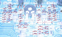
I had a hard time making out some of the board designations. This is what I have so far. There are definite differences in Q112 and 113.
Q112= 11.29, 11.97, 11.26
Q113= -30.8 -30.1, +2.8
Q110= 11.95 11.95, 10.38
Q118 C= -30.6 B= -30.1 E= -30.8
Q108 C= 30.6 B= 30.1 E= 30.8
R147 -15.10 R154 0V R153 -0.49 R155 0.38 R156 0V R157 -15.15 R158 0.47
R159 44V R161 OV R160 0V R149 0V R143 0V R145 1V R146 0.38 R140 0.71
R141 0.09 R152 0V R150 0V R142 0.08 R128 0.38 R127 -15.12 R129 0V
R130 15.16 R126 0V R125 -0.74 R151 0.43
- Status
- Not open for further replies.
- Home
- General Interest
- Car Audio
- Rockford 301s Won't power up