Stop please….
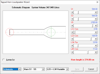
What you DREW was different from what you MODELED.
If the green is the mouth, then left pic is a stepped TH and right pic is a Paraflex enclosure.
Also, your tap point CANNOT be in the MIDDLE of a step transition.
You are basically stating that 1 driver is on the 90cm2 side and the other driver is on the 360cm2 side of the enclosure.
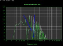
These 2 models prove my point.
You should NOT be able to ACCURATELY model a Paraflex enclosure with the TH function.
You can ACCURATELY model a TH enclosure with the PH function.
The PH function allows you to move the mouth regardless of the tap point.


You should NOT be able to ACCURATELY model a Paraflex enclosure with the TH function.
You can ACCURATELY model a TH enclosure with the PH function.
The PH function allows you to move the mouth regardless of the tap point.
You get that 120cm(72hz) reflection in that ‘paraflex’ or offset resonator qw pipe thingy
Exactly!
Maybe if you would build some of these boxes and measure the electrical impedances and Frequency response and overlay them with the horn response simulations in REW or something you would realize the things that you’re pointing out are completely irrelevant?What you DREW was different from what you MODELED.
If the green is the mouth, then left pic is a stepped TH and right pic is a Paraflex enclosure.
Also, your tap point CANNOT be in the MIDDLE of a step transition.
You are basically stating that 1 driver is on the 90cm2 side and the other driver is on the 360cm2 side of the enclosure.
View attachment 1371547vs View attachment 1371548
(or simply realize what the driver position in a resonator does and if the offset is so minuscule and high frequency , there’s no need to describe it or even worry about those detailed details)?? It’s a rabbit hole of things that don’t change anything . It seems horn response only needs to know the size and length of your resonators. And unless you’re going to do something drastically different with the driver position, then put it near the closed end none of that junk matters.?
I don’t know what/how that picture you drew with a huge offset resonator has anything to do with what I built or described to horn response
Last edited:
It’s pretty simple ? 20cm (432hz) of offset/details isn’t gonna tickle pickle
Attachments

Last edited:
Because YOU drew out a stepped TH and modeled it with the PH1 function, I was showing you the difference between a stepped TH and Paraflex.Maybe if you would build some of these boxes and measure the electrical impedances and Frequency response and overlay them with the horn response simulations in REW or something you would realize the things that you’re pointing out are completely irrelevant?
(or simply realize what the driver position in a resonator does and if the offset is so minuscule and high frequency , there’s no need to describe it or even worry about those detailed details)?? It’s a rabbit hole of things that don’t change anything . It seems horn response only needs to know the size and length of your resonators. And unless you’re going to do something drastically different with the driver position, then put it near the closed end none of that junk matters.?
I don’t know what/how that picture you drew with a huge offset resonator has anything to do with what I built or described to horn response
Using the PH1 function to model a stepped TH is the hard way of HR modeling, but it can be done.
I only build when I need to build.
New car, new build.
Damaged enclosure, new build.
Someone paying me for labor, new build.
HR modeling is fun to me. If folks choose to build or not build my models, so be it. I just like trying extract good performance out of any driver.
You should know by now that I could care less about what happens at 432hz when this is a SUBwoofer (<80hz) forum.It’s pretty simple ? 20cm (432hz) of offset/details isn’t gonna tickle pickle
You should know by now that I could care less about what happens at 432hz when this is a SUBwoofer (<80hz) forum.It’s pretty simple ? 20cm (432hz) of offset/details isn’t gonna tickle pickle
—> but all of the details you’re pointing out are only related to the frequencies which you don’t care about anyhow?
I don’t understand your point, and I used to think that some of those things mattered when you would bring them up

It’s just a tapped 1/4 wave pipe.Because YOU drew out a stepped TH and modeled it with the PH1 function, I was showing you the difference between a stepped TH and Paraflex.
Using the PH1 function to model a stepped TH is the hard way of HR modeling, but it can be done.
The top of the paraflex section is identical to the top of the tapped horn section as far as I can tell.
Whatever it is all of these things I keep building using that section end up measuring exactly the same as the horn response simulation. That includes parallel helmholtz resonators.
Attachments

A tapped 1/4 wave pipe = stepped TH in HR.
READ, the whole issue is you modeled a stepped TH with the PH1 function. It made me think you were contradicting your drawing by using a Paraflex function in HR. Most people would model that enclosure with the stepped feature within the TH function. Plus, you had a stepped transition between the 2 drivers in the PH1 model that did not line up with your drawing.
READ, the whole issue is you modeled a stepped TH with the PH1 function. It made me think you were contradicting your drawing by using a Paraflex function in HR. Most people would model that enclosure with the stepped feature within the TH function. Plus, you had a stepped transition between the 2 drivers in the PH1 model that did not line up with your drawing.
Have fun with this …
How is half the driver outside the throat?
I use a fosi v3 mono on each of my 8 channels. At 8 ohms I don't think they even push 200 watts. 7mm is enough. Thank you for the heads up.15W1600 have 7mm Xmax
15SW2000 have 12mm Xmax
For 20 bucks difference
It's just a representation of driver location in 2d. just imagine it turned 90°. It's no different than asking why the driver doesn't fit the pipe.How is half the driver outside the throat?
This description of the shape of that box is very inaccurate. Maybe they (Brian Steele, etc) were trying to use that angled shape to describe some of the volume that the motor and magnet are occupying instead of air?How is half the driver outside the throat?
None of these details make any sense, most don’t actually matter, however, none of these boxes seem to ever get an electrical impedance measurement and subsequent tweaks to the simulation methods to make them perfectly accurate through trial and error.
There are a few people who have built the roar and experienced a very disappointing/overdamped fundamental res. Is that because the upstream section is too small in crossectional area or because the driver used didn’t have enough motor force(or both)?
Have you built or heard one?There are a few people who have built the roar and experienced a very disappointing/overdamped fundamental res.
This description of the shape of that box is very inaccurate.
L12 = 0.90cm says different.
Let's see the HR input screen.
- Home
- Loudspeakers
- Subwoofers
- ROAR15