housing said:
Can you make 2 boards for me, please? I can send you some matched Jfets.............. 😀
Sorry housing, jfets are not my thing. What else do you have to trade?
😎
roender said:
MJL21193,
Good work!
Nice to see how fast you can make boards. What method do you use?
Regarding silkscreen, it's very difficult to create that layer with EAGLE
I look forward for how it sound impressions 😉
ps. It is a good time to change your nick name to NJL3281 🙂
Hi roender,
No, the MJL21193 took my virginity, broke my heart and sent my down this road from which there is no return... 😱
It's a shame that I can't import the file into Multisim/Ultiboard.
I have a couple of questions. The VAS is running at 8.25mA, correct? At the 39V rails that's about 320mW through the devices. The TO-126's will handle this easily, but the TO-92's are only 500mW. Is this pushing the limits of these transistors, or am I not seeing it correctly?
Also, what LED's did you use? Just standard 5mm? 2.2V, 20mA?
Hi John,
Maybe we can work something out for a pair of these PCBs. This looks very interesting.
I like J-Fets for differential pairs. I also like good BJT diff pairs.
-Chris 😉
Maybe we can work something out for a pair of these PCBs. This looks very interesting.
I like J-Fets for differential pairs. I also like good BJT diff pairs.
-Chris 😉
MJL21193 said:
Sorry housing, jfets are not my thing. What else do you have to trade?
😎
Hi roender,
No, the MJL21193 took my virginity, broke my heart and sent my down this road from which there is no return... 😱
It's a shame that I can't import the file into Multisim/Ultiboard.
I have a couple of questions. The VAS is running at 8.25mA, correct? At the 39V rails that's about 320mW through the devices. The TO-126's will handle this easily, but the TO-92's are only 500mW. Is this pushing the limits of these transistors, or am I not seeing it correctly?
Also, what LED's did you use? Just standard 5mm? 2.2V, 20mA?
John,
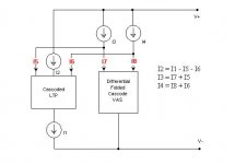
Please let me show you a picture of folded cascode working principle.
Differential FC VAS current is 2.2mA, I7 and I8 on the picture.
I5 and I6, LTP currents, are 6.1mA.
I1 is 13.2mA
I2, bias current for LTP cascoding devices, is 1mA
I have used 5x2mm rectangular shape LEDs. Please read all the post in this thread before staring to construct.
BRg,
M
Attachments
roender said:
John,
Please let me show you a picture of folded cascode working principle.
Ah, I see it now. Thank you. Slapping my head for not recognizing that the drop across these TO-92's is very small.
Here is what I will try:
I will use BC550 for J1 and J2, cutting the emitter leg short and solder a 180R directly onto the leg. I will increase R19 to 250R, this will change current through the LTP - each BC550 will see ~2mA.
Current through the VAS remains the same.
Do you see any problems?
Kirchhoff's Current Law:
At any point in an electrical circuit that does not represent a capacitor plate, the sum of currents flowing towards that point is equal to the sum of currents flowing away from that point.
Please apply this Law to the principle schematic posted above.
You will see that if you change the current into LTP you'll have to change the FC CCS currents if you want to keep the VAS unchanged, and i'll suggest you to leave the VAS unchanged
Please do the math yourself 😉
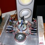
DRZ1 said:Mine is still sounding very well😀
Roender , do you have some problems with hum ? My FC100 seems to catch up 60hz by the front end. I'm in process to shield de front end.
What about your FC100 ?
Denis
Denis,
I think you have some ground wiring problem, or more than 92bB SPL speakers. 😀
Where did you put the speaker return wire? Into the star ground, in the middle of the board?
Attachments
roender said:
Please do the math yourself 😉
Hi roender,
Remember, I'm just a wood butcher brute pretending to know a thing or two about this. 😀
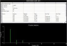
Math was never my strong suit. I'm lazy in this regard also, so I let the simulator tell me what's going on.
See currents below. This is with a pair of BC550 for diff pair, and 250 ohm R19. My LED's are 2.2V, 20mA. Is the sim doing something wrong?
Attachments
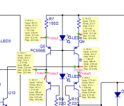
The VAS current is now over 8mA.
You must decrease the VAS CCSs currents to 4.2mA
Use this model for LEDs:
.model Gled D(Is=1e-22 Rs=6 N=1.7 Cjo=50p Iave=160m Vpk=5 mfg=Fairchild type=LED)
You must decrease the VAS CCSs currents to 4.2mA
Use this model for LEDs:
.model Gled D(Is=1e-22 Rs=6 N=1.7 Cjo=50p Iave=160m Vpk=5 mfg=Fairchild type=LED)
roender said:The VAS current is now over 8mA.
You must decrease the VAS CCSs currents to 4.2mA
Use this model for LEDs:
.model Gled D(Is=1e-22 Rs=6 N=1.7 Cjo=50p Iave=160m Vpk=5 mfg=Fairchild type=LED)
Hi,
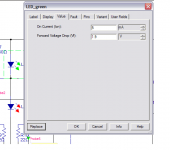
I can't change the model for an LED in Multisim, just the current and forward voltage. The LED's I will use for this are 20mA, 2.2V
On your schematic on page 1, you show the VAS current as 8.25mA. Is this not the case?
AndrewT said:if that's supposed to be an LTP then the two sides are not balanced!!!
Hi Andrew,
That (in my attachment) is the VAS.
same comment applies.
A balanced VAS sunk with a current mirror should have both sides balanced.
A balanced VAS sunk with a current mirror should have both sides balanced.
MJL21193 said:
On your schematic on page 1, you show the VAS current as 8.25mA. Is this not the case?
MJL2....John
You make a big confusion.
Active loaded (CCS) folded cascode VAS has 2.1mA bias current.
VAS CCSs, on top of folded cascode devices has VAS current + 1/2LTP current, in your case 2.1+2.1=4.2mA, in my case 2.1 + 6.2 = 8.3mA
Right?
M
AndrewT said:same comment applies.
A balanced VAS sunk with a current mirror should have both sides balanced.
Andrew,
Only with a floating current mirror, as in AD797 design, you can achieve a true balanced differential folded cascode VAS.
That type of mirror has the same impedance on both input and output sides.
hth,
M
roender said:
MJL2....John
You make a big confusion.
Ah...AH! My head is hurting from slapping it!
YES, now I see.
Sorry bout that. 🙂
I will make adjustments. Thanks.
MJL21193 said:Is this more like it?
Yes, you got it...You can add new LED model in Multisim, just edit regular model, copy/paste new spice model and save it in user model Led diode file.
aparatusonitus said:
Yes, you got it...You can add new LED model in Multisim, just edit regular model, copy/paste new spice model and save it in user model Led diode file.
Thanks,
I'll need to check the parts I have and pick the best fit to give this a trial run.
The MS I use doesn't have an accessible model for LED's, just the dialog as shown below. I could create a new part using the model posted by roender, but I don't think there is any need.
Attachments
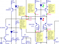
Here's the first working model of my version with bjt input:

I created a new board layout with all of the devices in a row.
After I figured out what I did wrong (trace routing had 2 of the NJL diodes reversed) it works. I'll need to put it on a heatsink for serious testing.
I created a new board layout with all of the devices in a row.
After I figured out what I did wrong (trace routing had 2 of the NJL diodes reversed) it works. I'll need to put it on a heatsink for serious testing.
- Home
- Amplifiers
- Solid State
- RMI-FC100, a single stage audio power amplifier