Group buy
Good afternoon Mihai, good afternoon all the other contributers and readers,
found this thread yesterday on my search for very good amps. Neither I am an expert, nor I am very experienced in building amps, but I have got good ears 🙂 and what I have read so far about this amp, let my wish growing to build a pair of these amps. My latest was a, guess, symasym, and, to be honest, I'm very happy with it, even I can imagine, there is room for more (both, amps and sonic).
Thats why I'd like to be considered in a groupbuy. I would take at least one or rather two pairs of this amp.
Thanks and regards
Ernst
Hi all
I would also like to build the amp. For now the problem for me is the availability of the transistors + proper 1st stage transformer - most of stocked ones 2x35V have high VA numbers which is not really needed. PCBs would be very nice too, although I could try etching them myself.
Greetings,
Pawel
I would also like to build the amp. For now the problem for me is the availability of the transistors + proper 1st stage transformer - most of stocked ones 2x35V have high VA numbers which is not really needed. PCBs would be very nice too, although I could try etching them myself.
Greetings,
Pawel
pzogal,
Try toroid-transformers.com they have a wide assortment of transformers from 25va up to 1.5kva. I have had very good results from their products. Tad
Try toroid-transformers.com they have a wide assortment of transformers from 25va up to 1.5kva. I have had very good results from their products. Tad
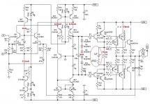
I've made a small design mod, as suggested by AKSA, with a very positive impact on bass control at high program levels.
C1 is now 1uF ERO MKT1813 (axial type)
The 0R82/0.6W, metal film resistor, in series with c1 is for avoiding ringing in driver transistors.
Thank you Hugh!
Mihai
C1 is now 1uF ERO MKT1813 (axial type)
The 0R82/0.6W, metal film resistor, in series with c1 is for avoiding ringing in driver transistors.
Thank you Hugh!
Mihai
Attachments
I'm looking for Hugh's comment, where should I look?roender said:Thank you Hugh!
What can I say?
You should use a foil, instead of metallised, polyprop in this position, very low dielectric absorption is important. Like the use of damping resistor, clever.....
I have tinkered with your basic circuit, Mihai, and come up with a modification which is single ended, grounded base with current gain.
Brings the OLG up to acceptable levels, and confers huge bandwidth and low distortion. Compensation is novel.
Again, thank you!!
Cheers,
Hugh
AKSA said:What can I say?
You should use a foil, instead of metallised, polyprop in this position, very low dielectric absorption is important.
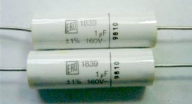
Sorry, regarding capacitor type, it was a mistake. The right capacitor series is Vishay Roedestein mkp1839.
The DA is only 0.05% (according to IEC 60384-1).
I'm at the office now, but when I'll get back home I will take and present hire a picture of the capacitor
Am I wrong in thinking MKT is metallized polyester, MKP is metallized polypropylene, and FKT/FKP are the film/foil types of these?
..Todd
..Todd
many manufacturers break the marking rules, or don't even use them.taj said:Am I wrong in thinking MKT is metallized polyester, MKP is metallized polypropylene, and FKT/FKP are the film/foil types of these?
..Todd
driver currents
Mihai,
Is it true to say that majority of the 77mA is coming from Q19 instead of Q3? Looks like Q3 only draws about 3-4mA?
Thanks,
Richard
Mihai,
Is it true to say that majority of the 77mA is coming from Q19 instead of Q3? Looks like Q3 only draws about 3-4mA?
Thanks,
Richard
Hi,
the CFP forces Vbe across R6 and this effectively operates Q19 at near constant current of just under 3mA.
All the remainder flows through Q3.
But, some current also flows to the output bases, possibly around 10mA.
Q3 will flow around 77+10-3~=84mA and dissipate ~2.8W. Keep them cool.
the CFP forces Vbe across R6 and this effectively operates Q19 at near constant current of just under 3mA.
All the remainder flows through Q3.
But, some current also flows to the output bases, possibly around 10mA.
Q3 will flow around 77+10-3~=84mA and dissipate ~2.8W. Keep them cool.
AndrewT said:... Q19 at near constant current of just under 3mA.
All the remainder flows through Q3.
...Q3 will flow around 77+10-3~=84mA and dissipate ~2.8W.
True!
Thanks Andrew
😉
Mihai,
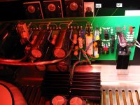
I particularly like the way you've inserted a rectangular green LED between two transistors, and then surrounded all with heatshrink to keep all at the same temperature.
A very neat, creative arrangement.... layout is IMPORTANT.
Cheers,
Hugh
I particularly like the way you've inserted a rectangular green LED between two transistors, and then surrounded all with heatshrink to keep all at the same temperature.
A very neat, creative arrangement.... layout is IMPORTANT.
Cheers,
Hugh
Mihai,
is it a material like heat shrink tubing or else you seem to use for the to-92 transistors so they are in close contact with each other?
Thanks
is it a material like heat shrink tubing or else you seem to use for the to-92 transistors so they are in close contact with each other?
Thanks
fab said:Mihai,
is it a material like heat shrink tubing?
Yes, there is nothing special ...
- Home
- Amplifiers
- Solid State
- RMI-FC100, a single stage audio power amplifier