This is the fifth day (120+ hrs) my Sapphire 3 has been powering my DT880’s, and fourth day with the ClarityCaps. It’s been on ‘round the clock. The roughness of new caps seems to be gone. The audio sounds fantastic. What I’m hearing through my DT880’s seems to agree with descriptions by the most insightful reviewers who’ve published reviews of these phones. I’m hearing the phones; I’m not hearing the amp. The amp is disappearing, which is, I think, as it should be. Can't imagine it being better than this, but I'll keep listening!
Remember that being powered on does not contribute to coupling cap break in, you have to be passing signal (the amp doesn't even have to be powered up, but the volume control should be turned up).
It's been passing signal continously at listening volume since my post of May 7. Itunes through airport Express digital out to Audioengine DAC to Sapphire. It's still on, I'll leave it on for a few more days.
Last edited:
Hi RJM,
I've started populating the boards and have a few questions for you.
1) Can I use a small sliding switch on the bottom of the case to switch from hi to low gain?
2) Plugging in the values for my Senheisser hd380 I get a gain of 6db. Using what I can find on the internet for say the Senheisser momentum I get something similar. Can I use values for 9db gain (12/1/22k) or is 15db a happy medium?
3) The resistors in the kit for R17/R18 are carbon and on brief testing seems +/- 5% or more. The BOM has (very expensive) 4.99ohm 1% vishays. Is the value or quality imprtant.
4) The resistors I have from the unbuilt S2 kit are 0.5W which are too big to lay flat. I thought of ordering from Mouser but wondering if I should use the Altronics 0.5W resistors I can buy locally which are slightly smaller than the Vishay 0.5W but I feel don’t sound the same. I have used them in one of my phonoclone builds.
I could just buy the resistors I need and build the S2 later and retire the original.
Thanks,
kffern
Last edited:
@Stan,
That's ok then. Should be cooked by now.
@Kevan,
1. Yes. Probably. No one has actually tried it yet. 😀
2. If the amp gain is more than 6 dB away from the recommended gain for your headphones, you should probably think about changing it or making it switchable.
3. The transistors Q9,10 are not matched to better than 5%, so in principle there is no need to use high tolerance resistors on the emitters. As you note Vishays are expensive and as I pointed out in a recent rant there is no good reason they cost $2 each, and certainly no benefit in this circuit. That said I have decided to use metal film for R17-20 in future, Mouser part 660-MF1/4DC4R75F and 660-MF1/4DC1R00F. While 5% is alright, carbon comp sometimes change value substantially on soldering, and one which is way out will screw up the bias substantially.
4. There is no need to have the resistors flat to the board. You can bend the leads into a "P" shape, like little standoffs. So if you have 1/2W Vishays you want to use you should be able to tuck them in reasonably tidily.
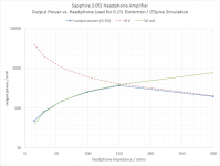
One more plot for today, this one is the traditional power output vs. load plot, with "clipping" set at a relatively strict 0.1% distortion.
Basically, the Sapphire buffer can put 50 mA rms into your headphones for any impedance 16-150 ohms. For higher loads the output is voltage limited. At 300 ohms the output can get up to 1.2 V from the voltage rails with minimal distortion.
If you are thinking "wow this would make a great preamp" .. yes, it would 😉
The preamp mod is to change R7,8,15,16 from 150 ohms to 475 ohms. It will still drive 600 ohms to +17 dB at <0.005% THD but reducing the bias currents like this means the input impedance goes up and heat/power consumption goes way down. I'd go back to using a 50k volume control and R2 100k.
Anyhow, returning to the headphone amp version, you can see from the graph that the "quotable" power output depends on headphone impedance and for 16-300 we must say "50 mW" For 60 ohms and up, however, its more like 200 mW. Totally academic, but formally the Sapphire output is therefore 50 mW.
P.S. The buffer circuit is what I'd like to call "super class A". It runs at 33 mA bias, so formally class A output current would be limited to about 20 mA rms. Because it's a push-pull output however, it actually pushes 50 mA rms before crossover distortion starts to bite. Since there's no feedback, this distortion creates a hard limit, and power output tracks the bias current just like a class A amp ... only slightly in excess of it rather than slightly under it as it would for a single-ended topology. Thus "super class A". I think Technics have already trademarked that one, though. 😀
Attachments
Last edited:
@Stan,
2. If the amp gain is more than 6 dB away from the recommended gain for your headphones, you should probably think about changing it or making it switchable.
i should have noted that my main HP is a HD650 but I do use the closed HD380 when people are around.
Kevan
HD650 is 300 ohms, 97 dB/mW -> recommended gain 26 dB (20k)
HD380 is 54 ohms 98 dB/mW -> recommended gain 18 dB (7k)
I think those sensitivities are correct, the original figures seem to be per V.
You could split the difference and go with ~20 dB fixed gain (R3 1k, R4 10k)
Or you could run with the BOM default values R3 4k7, R3A 1k5, R4 22k and switch hi/lo for the two headphones.
/R
P.S. The buffer circuit is what I'd like to call "super class A". ... I think Technics have already trademarked that one, though. 😀
Is this what you were thinking of? I have one of these old JVC "Super A" amps out in the garage. It sounds pretty good.
Attachments
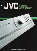
Yes it was, so it was Victor (JVC) not Technics then. I stand corrected.
I think that "Super A" was some sort of dynamic bias circuit, so its not related to what I was going on about earlier about the Sapphire buffer stage.
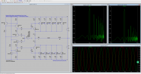
It's possible to watch what happens in LTSpice. As the output runs out of current the waveform clips, but before the output transistors run completely to zero it's more like the top of the sine wave is filed down rather than lopped off. In a single ended circuit it would be terrible 2nd harmonic distortion but push-pull they still cancel closely and the distortion stays low. Once the transistors turn "hard off" then it's a nasty mess.
Nothing unusual here, but in most SS amps the transition from class A to AB operation is just the midpoint, barely worth a mention, while for the Sapphire it signifies the end of the road. The Sapphire's working power envelope is defined by the class A power, with a 6~10 dB overhead.
The attached image shows the LTSpice circuit running 135 mW into 60 ohms. This is just at the edge where the transistors start to turn off completely but the current waveform is tangential to zero rather than hard up against it. The output shows about 0.02% harmonic distortion (3rd), while the current waveform in one half of the output stage (R15 in the circuit below) has 3% 2nd and 0.6% 3rd.
Classic, textbook stuff: push pull gives you lower distortion but proportionately more 3rd harmonic. This is why I love LTSpice: it makes it all real somehow.
I think that "Super A" was some sort of dynamic bias circuit, so its not related to what I was going on about earlier about the Sapphire buffer stage.
It's possible to watch what happens in LTSpice. As the output runs out of current the waveform clips, but before the output transistors run completely to zero it's more like the top of the sine wave is filed down rather than lopped off. In a single ended circuit it would be terrible 2nd harmonic distortion but push-pull they still cancel closely and the distortion stays low. Once the transistors turn "hard off" then it's a nasty mess.
Nothing unusual here, but in most SS amps the transition from class A to AB operation is just the midpoint, barely worth a mention, while for the Sapphire it signifies the end of the road. The Sapphire's working power envelope is defined by the class A power, with a 6~10 dB overhead.
The attached image shows the LTSpice circuit running 135 mW into 60 ohms. This is just at the edge where the transistors start to turn off completely but the current waveform is tangential to zero rather than hard up against it. The output shows about 0.02% harmonic distortion (3rd), while the current waveform in one half of the output stage (R15 in the circuit below) has 3% 2nd and 0.6% 3rd.
Classic, textbook stuff: push pull gives you lower distortion but proportionately more 3rd harmonic. This is why I love LTSpice: it makes it all real somehow.
Attachments
Last edited:
I've updated the Sapphire web page to version 3.0. All assets (BOM, etc.) are available to download.
RJM Audio - Sapphire headphone amplifier
RJM Audio - Sapphire headphone amplifier
With new Z-Reg PSU schematic, the current passed to zenner will be less than 5mA (stated in your Sapphire page) (may be half). Does it affect anything?
For 18 V V++, 12 V Zener, that's 6 V dropped through 2 k (R23 + R25) ... 3 mA.
Indeed its a bit less than 5 mA now, but I think anything over 1-2 mA is plenty. The minimum current to turn on the 12 V Zener is 0.25 mA. The Zener is just feeding the base of Q12 through R27, its a light load so the slight increase in impedance shouldn't matter.
Indeed its a bit less than 5 mA now, but I think anything over 1-2 mA is plenty. The minimum current to turn on the 12 V Zener is 0.25 mA. The Zener is just feeding the base of Q12 through R27, its a light load so the slight increase in impedance shouldn't matter.
Going on nine days running-in Sapphire 3
Since my last report, three+ more days of continuous playback at a "stout" listening level, passing signal (not just powered on). I thought this couldn't get any better, but I'm quite certain that it has. I suppose I am hearing the further bedding in of the ClarityCap MR input coupling caps that I switched in after day one. There has been a small but noticeable further improvement of spatial presentation; improvement in separation of voices, instruments, clarity, a purity I have not heard through headphones before. This is the level of sonic discrimination I was hoping for. Sound quality is just lovely, I am so enjoying it. Been trolling my music library hearing what things really sound like, and the things I've missed. Extremely pleased with Sapphire.
To be honest, I have not done a lot of critical listening for many years - once in a while, yes, but fine speakers in an only haphazard listening room; building a Sapphire was a means to get serious about headphone sound quality. The headphone amp in my Dacmagic Plus was disappointing, though the DAC is quite good. The AudioEngine D1 headphone out is good, but Sapphire 3 has left it behind. I bought my DT880's about seven months ago and I think I am now, just in the last few days, hearing what they are truly capable of. Very pleased with them, too.
Going back to the cap reviews at Humble Homemade Hifi, which I read through before deciding what caps to buy/try, what I'm hearing corresponds very well, indeed, to the description of the MR there (ClarityCap MR is one of the reviewer's - Tony Gee, I think - favourites).
There's no penalty, electrically, to the normal operation of the circuit if you do. It's just a safety thing. A safety thing I strongly recommend. Maybe try it briefly with C1 bypassed with a shorting wire under controlled conditions, to convince yourself the cap does not, in fact, make such a huge difference, and what it does add isn't unpleasant.
I'm just back from matching 100 BC337 and 100 BC327 transistors for the Sapphire kits.
(spare a thought for how much of a pain in the butt that is...)
Anyway, its interesting how different the PNP and PNP hfe spread is. I'm using the "-25" class, which are spec'd for hFE1 160~400.
The BC337 group very tightly, 95% of them fall within 240-260. The rest, though, are crazies, generally up around 280-340, but highly scattered.
The BC227 are a more typical Gaussian distribution, centered about 300, and 80% of them within 280-320 and most of the remaining just outside that range.
The kits ship with transistors of each type grouped within 20 of each other, but the NPN and PNP bins are not the same. That's not possible without buying thousands of tranistors and throwing away 90% of them. So I guess they are screened/binnedrather than matched. Given the symmetry of the unity gain buffer circuit that's not a problem.
What is a (okay, still small) problem is if you don't screen the transistors and get one or two of those crazy BC337s in your circuit. It's probably enough to mess up your bias currents and/or output offsets, as I found in my first build.
Last edited:
I checked all the transistors in my kits and found the HFE to vary but the VBE to be spot on - same for all of them. Was the bad transistor in your earlier build off in VBE measurement as well as HFE?
I didn't check. The transistors I sent you were binned in the same way as I described above, with HFE all within a range of <30.
- Home
- Amplifiers
- Headphone Systems
- RJM Audio Sapphire Desktop Headphone Amplifier