I m in the process of researching for a passive preamp for my setup and I am now working on a lightspeed variant with its output attached to a Lundahl 1592 1:1+1 transformer with one of its secondaries reversed so that I can get a proper balanced XLR output to drive my Electrocompaniet AW120 DBM (200k input impedance).
What worries me is that my sources may not have enough "juice" to drive the transformer after the passive attenuator, so I was looking for some kind of buffer to solve that problem for me and allow for some bigger interconnects after the transformers.
You think the B Board might be a good fit for my case?
Thanks in advance.
While still in the early stages of beta-testing, the B-board is cheap enough, and simple enough, that if you have space in your case to experiment I advise that you give it a try.
I expect it should do what you want, it's just at this point I can't guarantee it.
I expect it should do what you want, it's just at this point I can't guarantee it.
B-board test mule
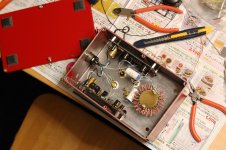
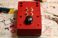
To test the B-board buffer modules, I stripped my Gainclone and transformed it into a buffered volume control. (Think of it as a preamplifier with no gain and no functionality other than a volume control.)
The volume control goes to 2.2uF* film coupling capacitors, which run to the B-boards with 100k resistor across the inputs.
Works fine, gain is a fraction low of course but its certainly quiet! Output offsets are about 50 mV.
Need to let it break in for a couple of days.
Unfortunately its going to be a bit difficult to make an evaluation, since the influence on the sound is going to be quite small I expect, and I don't have anything obvious to switch it out for to make a comparison.
* 0.47 uF is sufficient, I just didn't have that value on hand.
Attachments
Last edited:
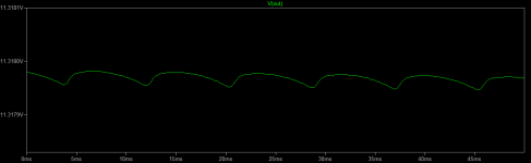
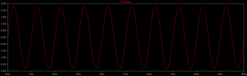
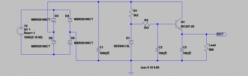
ltspice files for the B-board including the simulation for the Z-reg voltage regulator. For the 15 mA or so current drawn by the buffer, the Z-reg output ripple is about 30 microvolts.
PSRR of the buffer circuit is about -50 dB.
PSRR of the buffer circuit is about -50 dB.
Attachments
Simple test, just to confirm what my ears already told me: a clean bill of health.
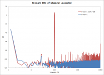
It's a unity gain line buffer with a regulated power supply. If its working properly, it's going to be essentially below the measurement threshold of my instruments. Indeed this is the case here.
With the volume at -inf, the output noise is below the measurement baseline of ~-115 dB. The peak at 28 Hz is an artifact of the test setup/instrumentation. There is no measurable hum or noise.
Applying a 100 Hz sine wave of 2.8 V amplitude (+6 dB), there is no measurable distortion above the digital sampling artifacts of the function generator which spread out evenly at around -90 dB for all higher harmonics.
(not shown) Above amplitude 5 V (about +12 dB) clipping distortion is evident.
Measurements taken with a National Instruments USB-6215 multi-function DAQ.
Attachments
So how does it sound?
Well, if I close my eyes, it is easy to imagine I'm listening to a high end pre-amplifier. It adds nothing but a slight sense of authority and a certain "lift", that micro-detail that seems to lend the music that little bit of extra realism. Perhaps. That's my impression, but I haven't done any direct comparison with the passive, unbuffered output of the attenuator yet.
I like it, anyway. "It" is subtle, perhaps very little, but whatever is there is, I'm convinced, a positive effect.
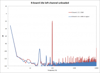
Re-did the measurement at a slightly improved sensitivity setting. The measurement limit is -139 dB. The B-board output is perfectly clean, no ripple noise right down to this limit. (30/60/90 Hz peaks are measurement artifacts) The distortion signal of a -20 dB sinewave is also very clean, nothing visible right down to the digital noise of the function generator.
Long story short: a cannot "see" the B-board with my measurements, and, frankly, I can barely hear it either. It is transparent, while fulfilling it's role as a buffer.
Mission accomplished!
Long story short: a cannot "see" the B-board with my measurements, and, frankly, I can barely hear it either. It is transparent, while fulfilling it's role as a buffer.
Mission accomplished!
Attachments
I am still experimenting with my lightspeed clone, and it sounds a bit thin-ish.
The attenuator works like a ~8k pot.
Do you think the topology you describe above would work nicely with it?
The attenuator works like a ~8k pot.
Do you think the topology you describe above would work nicely with it?
Yes, you should be able to connect the B-board/Sapphire directly to the output of the attenuator.
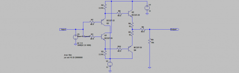
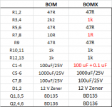
To check a few things, I'm building a second set with an experimental BOM, BOMX below.
- Emitter resistors R3,4 lowered to 1k to increase the bias current.
- Emitter resistors R7,8 lowered to 1R, which raises the bias current in the output stage to more closely match the driver stage, at the expense of stability and increased likelihood of thermal runaway.
- Ceramic bypass caps added in parallel to the four electrolytics after the Z-reg. If there is any high frequency stability issues, this should quiet things down.
Attachments
For reasons explained in my blog post, I'm fairly confident that of the changes made (3) above made a very large improvement. For some reason, adding ceramic bypass capacitors sweetened up the treble, removed glare, and generally improved the musicality.
According to the simulation the diamond buffer bandwidth is about 4 MHz, clearly higher than the usable range of the electrolytics, which extends to perhaps 1 MHz. On the other hand there is no signal energy up there, and even if there was it would be inaudible, and furthermore the circuit is not in any kind of feedback loop, so I wouldn't have expected any instability or indeed great effect on the sound. But there you are, if I had expected it I would have built it that way in the first place.
According to the simulation the diamond buffer bandwidth is about 4 MHz, clearly higher than the usable range of the electrolytics, which extends to perhaps 1 MHz. On the other hand there is no signal energy up there, and even if there was it would be inaudible, and furthermore the circuit is not in any kind of feedback loop, so I wouldn't have expected any instability or indeed great effect on the sound. But there you are, if I had expected it I would have built it that way in the first place.
Will you have any more boards available for this ? After a simple pot buffer for a preamp I'm building - this looks ideal 🙂
Ray, I have kits available but not the individual boards right now. I will definitely be making a new batch of boards and kits, but not for a few months at least.
I just got some new speakers, and I am flirting with the idea of biamping them.
Do you think we could use 2 buffers per channel in parallel after an attenuator to drive the four total channels?
Do you think we could use 2 buffers per channel in parallel after an attenuator to drive the four total channels?
So just two of them in parallel?
Do you think R1 and R2 will have to be matched or something? On all 4 channels?
Do you think R1 and R2 will have to be matched or something? On all 4 channels?
By the way, I just received the b-boards. I will try to start working on them today (as output stage of lightspeed) and get back to you.
OK just finished soldering and cleaning the boards.
Once again, nice job Richard. I m too tired to do any tests now, but I will definetely do tomorrow.
My only remark is again the size of the pads. Especially with the carbon resistors and the big ground planes. It can easily get messy and you cannot see if the solder has flown on the pad or has created a blob on the wire.
(I m using 0,46mm multicore solder and an Ersa station with a 2mm chisel tip @450 Celcius)
Sorry about the pad size. It's the default in Eagle, and changing it is non-trivial.
Re. parallel, yes, just feed the attenuation output into as many B-boards as you need. No need to match anything, or any other special precautions. What you are asking for is exactly the job buffers are designed to do.
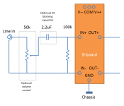
See circuit in post 23 for the details of configuring the B-board with a volume control. The coupling capacitor may not seem like its necessary, and in many ways its not, but what it does do is make the output DC offset of the B-board independent of the volume setting. Without it you may hear "clicks" when changing volume if you are using a stepped attenuator.
Re. parallel, yes, just feed the attenuation output into as many B-boards as you need. No need to match anything, or any other special precautions. What you are asking for is exactly the job buffers are designed to do.
See circuit in post 23 for the details of configuring the B-board with a volume control. The coupling capacitor may not seem like its necessary, and in many ways its not, but what it does do is make the output DC offset of the B-board independent of the volume setting. Without it you may hear "clicks" when changing volume if you are using a stepped attenuator.
Last edited:
- Status
- Not open for further replies.
- Home
- Source & Line
- Analog Line Level
- RJM Audio B-Board Project