For someone always asking for a firm prove, this is an unworthy speculative answer.Problem is, some never realize they are on a learning curve, and end up forever in the simulation realm.
As of chopping heads and discussion tone, that's in the eye of the beholder. You are, as far as I can tell, a mostly simulation only expert, irritated by anything that goes beyond your LTSpice computer screen, and using your simulator for clubbing everything. That, without any further attempt to interpret the simulation results and understand the underlying causalities, while "this is what simulation says" and "why don't you simulate it" are the absolute arguments. You are not the only one here, the Homo Simulantis species is spreading like a disease. There, you asked for it 😀.
Fact is that you haven't got a clue what I have designed and realised.
And yes, redoing the PCB after the first iteration is not just your experience, but that does in no way degrade simulation as being a very valuable and fantastic pre building tool.
It's completely unrealistic to expect 100% perfection, just live with 90% with all its limitations not in the last place because the PCB itself is also an integral part of the design.
Since I'm no beholder like JC, Richard Lee or Bob Cordell to name just a few of many, I nevertheless always feel embarrassed when I read your postings to them or about them.
I see no reason at all to damage people in such a way and that was exactly the reason for my previous posting.
But thanks for calling me a Simulation Expert, I see that as a compliment.😀
Hans
I can send you some HPS versions for free (I have them all since 1.0), but you are not going to like the shipping fees. About the common base boards in this thread, give me a couple of weeks and I'll send you a couple (for stereo) of the new fully assembled boards for free, i'm afraid I already butchered the old version boards. They'd fit in a padded envelope, no problem with shipping.
I do have a smuggling route via California to reduce postal costs 🙂. I am overdue a visit to there as well.
Ref the Holman paper and again way off topic each time I read it there are things I feel really ought to be retested in the light of where we are in 2019 with this obsolete format. Of course many might not like the answers esp if its found out that a vintage V15V with a Jico replacement stylus is actually the most accurate reproducer (in the right tonearm).
For someone always asking for a firm prove, this is an unworthy speculative answer.
Fact is that you haven't got a clue what I have designed and realised.
And yes, redoing the PCB after the first iteration is not just your experience, but that does in no way degrade simulation as being a very valuable and fantastic pre building tool.
It's completely unrealistic to expect 100% perfection, just live with 90% with all its limitations not in the last place because the PCB itself is also an integral part of the design.
Since I'm no beholder like JC, Richard Lee or Bob Cordell to name just a few of many, I nevertheless always feel embarrassed when I read your postings to them or about them.
I see no reason at all to damage people in such a way and that was exactly the reason for my previous posting.
But thanks for calling me a Simulation Expert, I see that as a compliment.😀
Hans
... and nobody claimed that his simulation results are 100% reflecting performance of the real physical circuit.
Almost all simulation results presented here so far contributed to show trends, limitations and getting better insight in dependencies between the various component choices and operating points and observed performance.
All the findings are no absolute rule to build a circuit the one and only way but it's up to you to make appropriate selections according to your preferences - there is no absolute true or false.
And yes, the final proof are measurements with real circuits and then optimize those aspects that can not be simulated like quality of used parts, selecting parts for certain parameters, make better PCB layouts, get rid of hum and interferences ....
Bonsai,Sorry Hans, but my speaker cones flap in and out at about 0.5Hz. I can see it.
Did you already have the opportunity to read the B&K paper?
In fact there is a strong relation between the LF spectrum below 15Hz of the vertical movement of the cart and the FM modulation of the signal.
See image below of an example of the actual frequency of an 3150Hz recorded tone over 2 revolutions on an LP and the spectrum of the signal modulating this 3150Hz.
The lower part is made by LD, the upper part from my hand, showing the same, but in a somewhat higher resolution.
What you can see in the FR of the modulating signal, is the flapping of your cone as the strongest component.
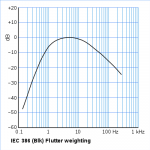
But there are much more components to be seen, where especially our auditory system is most sensitive for modulation components in the 4-8Hz region.
That's why there is a IEC386 filter that focusses on the audio band of our highest sensitivity.
And that's also the reason why you should stay away with fres Cart from this region.
Hans
Attachments

syn08,
In relation to your post as quoted by Hans who is in fact a recognised author in Linear Audio why bother posting at all if you are so superior?
It seems you enjoy narcissistic self indulgence which is neither welcome or in the spirit of diy Audio.
Btw it took you five successive attempts to come up with your ultimate phono stage.
Were you show boating or just learning?
Yes, self promoting. Unlike yours, my sales are slumping and I need a boost 😀.
Thanks. No data (or justification) on the 20mS group delay audibility threshold, the standards are hugely over this value, even at 50Hz. Next simulation, please 😀.
Clearly you did not look at fig. 7. Holman took data from a number of sources and plotted them on a graph (a 'meta' study if you will). The graph is intended to show the limits of group delay audibility* - as they were understood in the 1970's when this article was written - and include the DIN standard curve as well.
The reason I brought this up was simply to make the point that when looking at most of these subsonic filters (Self et al), the GD is well below the curves shown in Holman's article and should therefore be inaudible.
But, again, you discard other peoples sources and opinions and plough on with your story regardless. Please don't pollute this thread any further.
* I have pointed out that the Y axis in his plot is mislabelled in seconds and should read milli-seconds
Bonsai,
Did you already have the opportunity to read the B&K paper?
In fact there is a strong relation between the LF spectrum below 15Hz of the vertical movement of the cart and the FM modulation of the signal.
See image below of an example of the actual frequency of an 3150Hz recorded tone over 2 revolutions on an LP and the spectrum of the signal modulating this 3150Hz.
The lower part is made by LD, the upper part from my hand, showing the same, but in a somewhat higher resolution.
What you can see in the FR of the modulating signal, is the flapping of your cone as the strongest component.
But there are much more components to be seen, where especially our auditory system is most sensitive for modulation components in the 4-8Hz region.
That's why there is a IEC386 filter that focusses on the audio band of our highest sensitivity.
And that's also the reason why you should stay away with fres Cart from this region.
Hans
Yes -I read it - thanks for that and I am clearer now about the Fres thing as well as Bill's reason for preferring it in the 11-14 Hz range. Clearly once the signal has been polluted with Fres harmonic components folding up into the audible band the damage is already done (c.f. the B&K article). I still don't like clone flap from warped records though!
Last edited:
Clearly you did not look at fig. 7. Holman took data from a number of sources and plotted them on a graph (a 'meta' study if you will). The graph is intended to show the limits of group delay audibility* - as they were understood in the 1970's when this article was written - and include the DIN standard curve as well.
I did. Again. Then again again. No justification on why 20mS should be the upper limit for the rumble filter group delay @20Hz (filter is “one fortieth” of the standards @50Hz). Once again, the audibility and DIN thresholds are orders of magnitude higher than his example filter, with or without arm + cartridge contribution.
We must live in parallel universes if you see in fig. 7 more than that. I’m starting to believe we may disagree even on the probability of a sunrise tomorrow. No surprise, LTSpice doesn’t model it.
Last edited:
Blimey hans, that FM polar is awful. What deck is it, you can see cogging, suspension and warp errors.
Heres one that at least goes round in a circle
sq_kuzma_polar | Simon Clarke | Flickr
Heres one that at least goes round in a circle
sq_kuzma_polar | Simon Clarke | Flickr
Nice plots - but what is the frequency axis and it's resolution? The most important axis is not labeled.
Depending on the selected scale and resolution, you can make any curve look smooth or wildly bumping.
Depending on the selected scale and resolution, you can make any curve look smooth or wildly bumping.
Blimey hans, that FM polar is awful. What deck is it, you can see cogging, suspension and warp errors.
Heres one that at least goes round in a circle
sq_kuzma_polar | Simon Clarke | Flickr
Is it an idler TT, the 4 Hz could be caused by the idler wheel if so? And the oval shape may be due to platter errors.
Just a thought.
Blimey hans, that FM polar is awful. What deck is it, you can see cogging, suspension and warp errors.
That was chosen I believe as a particularly bad example to show all the effects (including eccentricity).
Is it an idler TT, the 4 Hz could be caused by the idler wheel if so? And the oval shape may be due to platter errors.
Just a thought.
Several of us did a version of this tool that anyone can use for free in another thread that has been idle for a while (you do need Python). The frequency is labeled radially so if you use a 1K reference tone 1Hz "ticks" are 0.1%. The warped shape to the circle is LP eccentricity which gets slightly elliptical because, if you think of the geometry of the plot you are actually projecting an off center circle onto a conical surface (because the frequency ticks are evenly spaced).
IIRC a typical 300rpm belt drive gives a 9Hz artifact. One user with a perfectly centered test LP and a very good Lenco made an almost perfect circle.
NOTE - You can do this without the polar plot in any tool like Octave or Matlab using a filtered Hilbert transform which is built into all of the math libraries.
Last edited:
Blimey hans, that FM polar is awful. What deck is it, you can see cogging, suspension and warp errors.
Heres one that at least goes round in a circle
sq_kuzma_polar | Simon Clarke | Flickr
When it's your Kuzma, you have a fine TT.
Plots are just a question of magnification.
Your plots won't be that different on a different scale.
I can't remember what deck it was, but it was not at all exeptionally bad.
Hans
Andreas, you are quite right right.Nice plots - but what is the frequency axis and it's resolution? The most important axis is not labeled.
Depending on the selected scale and resolution, you can make any curve look smooth or wildly bumping.
The frequency axis is the spectrum of the signal modulating the 3150Hz from the LP caused by warp etc, etc., but not yet filtered by IEC386.
The vertical axis shows the rms value of the wow at a certain frequency, where 1mV corresponds to 0.1% rms.
Rms value of the modulating signal in the time plot, should be below 0.1% after IEC386 to be inaudible according to DIN and that's what most recordings meet, although more expensive turntables show figures at 0.04% or even below.
This sample isn't quite as bad as it looks and meets, when I rember correctly, something like 0.05% wow after IEC386.
Hans
The scale on mine is %, the Mober was a shade over 0.02%. I'll see if I have on for my current setup with dc tachometer and thick silicon oil in the bearing, it's a chunk of change better.
I did. Again. Then again again. No justification on why 20mS should be the upper limit for the rumble filter group delay @20Hz (filter is “one fortieth” of the standards @50Hz). Once again, the audibility and DIN thresholds are orders of magnitude higher than his example filter, with or without arm + cartridge contribution.
We must live in parallel universes if you see in fig. 7 more than that. I’m starting to believe we may disagree even on the probability of a sunrise tomorrow. No surprise, LTSpice doesn’t model it.
More blah blah blah . . .
More blah blah blah . . .
Understood. You have no data to show.
Ref the Holman paper and again way off topic each time I read it there are things I feel really ought to be retested in the light of where we are in 2019 with this obsolete format. Of course many might not like the answers esp if its found out that a vintage V15V with a Jico replacement stylus is actually the most accurate reproducer (in the right tonearm).
Just got my Jico, unfortunately to be fitted into an Ultra 500, slightly over 9 grams (!), so testing should be possible. I have the old Shure test records, but I'm unclear about a way to make subsonic sweeps. Any suggestions are welcome.
Much thanks, as always,
Chris
- Home
- Source & Line
- Analogue Source
- Richard Lee's Ultra low Noise MC Head Amp