Thanks for this Guru Hans. I was about to exit beach bum mode, get LTspice running on a computer and see if I can still pre10 to use it 🙂So far I examined Richard's Duraglit mainly on noise, collector current and Rs.
Now I looked at the FR and noticed that depending on Rs and collector current, there can be a nasty bump below 10Hz when using 470uF caps.
The lower Rs, the larger the bump.
With Rs = 5 Ohm, it can already be as much as 7 dB, getting even larger for lower values.
The remedy is to alter these caps into at least 5mF as can be seen in the image below where 0.5mF and 5mF are both used for Rs=5R and Rs=17.5R
Your Fig4 in #655 shows Duraglit actually has the topology of a fancy HP filter (whose name I've forgotten) which I've used in an unrelated commercial product. I would want to build proper subsonic filtering into a matched device so might do more work later. Da beach bum stuff is a boat so this might never happen 😀
What current is this sim at?
Last edited:
Now I looked at the FR and noticed that depending on Rs and collector current, there can be a nasty bump below 10Hz when using 470uF caps.
Exactly the reason why in https://www.diyaudio.com/forums/ana...tra-low-noise-mc-head-amp-38.html#post5841706 I used 7,800uF (2x3,900uF polymer) on each half.
Exactly the reason why in https://www.diyaudio.com/forums/ana...tra-low-noise-mc-head-amp-38.html#post5841706 I used 7,800uF (2x3,900uF polymer) on each half.
O.k. In that case, everything under control 👍
Hans
Be careful with these Poly Alu electrolytics.
I gave up on feedback for my wideband lo noise amplifier because I could not get
1 or 2 MHz BW without negative input impedance which I find unacceptable for
a lab tool. Yes, damping everything to death works, but then the BW is gone.
I wanted really high input impedance, so I grounded the gate via 10 to 100 Meg with
an analog switch to decrease that, if the operating point is out of bounds.
Gain with a FET goes with rt(Id) and over a range of 30°C the change was not acceptable.
I enforced the source current to 27 mA with a CCS made from a FZT851 mirror.
That's not too much current for 2 IF3601. To keep the source at AC GND, I used
Poly alu 4700uF / 2V5 * others for RF. DigiKey 493-4582-1-ND
2V5 should be OK for +500mV for Vgs. Did I think.
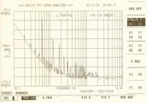
That resulted in the purple function in the picture. 30 dB/decade from 300 Hz downward.
Low cost normal ALUs 3300u/10V healed that. Wet slug tantalum was not better.
There is still 0.8dB/10K gain change in simulation. Attributable only to the FET.
I'll heat it to constant 35°C.
I gave up on feedback for my wideband lo noise amplifier because I could not get
1 or 2 MHz BW without negative input impedance which I find unacceptable for
a lab tool. Yes, damping everything to death works, but then the BW is gone.
I wanted really high input impedance, so I grounded the gate via 10 to 100 Meg with
an analog switch to decrease that, if the operating point is out of bounds.
Gain with a FET goes with rt(Id) and over a range of 30°C the change was not acceptable.
I enforced the source current to 27 mA with a CCS made from a FZT851 mirror.
That's not too much current for 2 IF3601. To keep the source at AC GND, I used
Poly alu 4700uF / 2V5 * others for RF. DigiKey 493-4582-1-ND
2V5 should be OK for +500mV for Vgs. Did I think.
That resulted in the purple function in the picture. 30 dB/decade from 300 Hz downward.
Low cost normal ALUs 3300u/10V healed that. Wet slug tantalum was not better.
There is still 0.8dB/10K gain change in simulation. Attributable only to the FET.
I'll heat it to constant 35°C.
Attachments

Last edited:
Be careful with these Poly Alu electrolytics.
I gave up on feedback for my wideband lo noise amplifier because I could not get
1 or 2 MHz BW without negative input impedance which I find unacceptable for
a lab tool. Yes, damping everything to death works, but then the BW is gone.
I wanted really high input impedance, so I grounded the gate via 10 to 100 Meg with
an analog switch to decrease that, if the operating point is out of bounds.
Gain with a FET goes with rt(Id) and over a range of 30°C the change was not acceptable.
I enforced the source current to 27 mA with a CCS made from a FZT851 mirror.
That's not too much current for 2 IF3601. To keep the source at AC GND, I used
Poly alu 4700uF / 2V5 * others for RF. DigiKey 493-4582-1-ND
2V5 should be OK for +500mV for Vgs. Did I think.
That resulted in the purple function in the picture. 30 dB/decade from 300 Hz downward.
Low cost normal ALUs 3300u/10V healed that. Wet slug tantalum was not better.
There is still 0.8dB/10K gain change in simulation. Attributable only to the FET.
I'll heat it to constant 35°C.
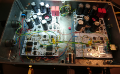
Not a problem with the bipolars in https://www.diyaudio.com/forums/ana...tra-low-noise-mc-head-amp-38.html#post5841706, although I did not care of the HF response. Gain is 27dB, noise RTI about 0.25nV/rtHz (best try). Average was around 0.3nV/rtHz. Gain is 27dB, input shorted.
Attachments
Not a problem with the bipolars in https://www.diyaudio.com/forums/ana...tra-low-noise-mc-head-amp-38.html#post5841706, although I did not care of the HF response. Gain is 27dB, noise RTI about 0.25nV/rtHz (best try). Average was around 0.3nV/rtHz. Gain is 27dB, input shorted.
That is 4ohm equivalent: 4/2=2ohm Rbb', 1/2=0.5ohm emitter, 1.2/2=0.6ohm collector current noise contribution (1/2gm @ about 10mA), about 1ohm is everything else. Not much left for the alu polymer caps PLG0E392MDO1 Nichicon | Capacitors | DigiKey from a bag of 20, I must have been lucky.
Transistors were extinct Rohm 2SD786/2SB737, the Zetex ZTX851/ZTX951 devices are as good... if you are lucky. I found 2 competitive (with the Rohm devices) pairs of Zetex devices out of 10, the variation is quite large, and it's not Rbb' at fault. Rather a high (for bipolars) noise corner frequency and apparently high G-R noise. Exactly what I was expecting from devices not intended for low noise.
Last edited:
There is probably no problem with the DigiKey 493-4582-1-ND Poly Alus in a
low impedance environment, such as filtering a LiPo battery, but when used to keep
the output of a dc current source at AC 0V, every charge packet that defects through
the cap produces telegraph noise. (is telegraph 1/f**3 ?)
I'm not interested in circuits here, it's just that el Cheapo 1189-1056-ND 3300u/10V
ordinay alu electrolytic does not produce that effect.
I got some mechanically larger caps in the mean time that cost more but are promised
to survive longer at 105°/125°C (still 12.5mm dia). The results are still out.
I have used them in the second channel of the cross correlation machine; if they
perform there, the first channel will be updated.
One could also try 10V organic, but I'm seeing signs of operator exhaustion.
There is always so much one could test additionally.
That could be used for stereo, at least the input stage, but it's for cross correlation.
Attachments
the cap produces telegraph noise. (is telegraph 1/f**3 ?)
This would be strange, since telegraph noise (aka popcorn noise) is normally associated with micro defects in semiconductors and/or heavy metal contamination, being therefore strongly process dependent. Not much to do with the electrolytic capacitors physics. Typically, popcorn noise doesn't have a Gaussian distribution, but a trimodal distribution inherited from 1/f and Johnson noise, shifted by the popcorn noise. The power spectral density of the popcorn noise is ~1/f^a where a=1...2, usually closer to 1/f^2, definitely not 1/f^3. It is fair to say that modern semiconductor manufacturing processes made the popcorn noise largely a non issue.
If you look into datasheets for electrolytics/organics the specified the specified ESR can be very low for the organics but leakage current is at least 10-fold higher than for ordinary (low leakage) alu electrolytics.
Leakage currents are currents due to random defects in the microscopic thin alu-oxide layer. These then are healing again (by oxidation) by the flowing current. Beeing random in nature, this must result in noise currents. These processes are typically low frequency and thus should follow some 1/f***x function with x beeing highly dependant on technology and manufacturing conditions.
Same happens in Tantals and that's what Richard already reported in his original article as 'crackling' noise.
(is telegraph 1/f**3 ?)
Not typically. I have observed GR noise at frequencies as low as .01Hz with its region of 1/f**2 which returned to 1/f behavior at .000011Hz (and yes I measured it).
You do not need very large capacitors from the bases of the transistors to ground in Richards Duraglit. The cure is to insert 2 damper resistors in series with the output caps as shown below. Values of between 220 and 470 Ohms do the job.
There is no impact on the noise performance.
There is no impact on the noise performance.
Attachments
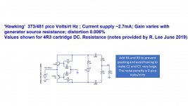
For some reason, I used 22uF output caps all the time, instead of the 220uF as you have used.You do not need very large capacitors from the bases of the transistors to ground in Richards Duraglit. The cure is to insert 2 damper resistors in series with the output caps as shown below. Values of between 220 and 470 Ohms do the job.
There is no impact on the noise performance.
This changes the behaviour a bit.
But inserting 2* 220R into the output line, doesn't makes things better in the example I gave yesterday, on the contrary.
You will still need large caps for the other 2.
Hans
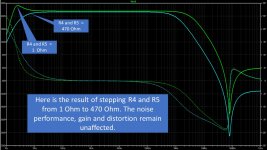
Here are the plots for R4 and R5 at 470 Ohm. As you say, even with 220uF capacitors in the transistor bases you still have the sub-sonic bump, but this trick avoids that you have to use very large (>> 1000uF) caps in the bases with no penalty to get rid of the bump.
Attachments
Last edited:
Here are the plots for R4 and R5 at 470 Ohm. As you say, even with 220uF capacitors in the transistor bases you still have the sub-sonic bump, but this trick avoids that you have to use very large (>> 1000uF) caps in the bases with no penalty to get rid of the bump.
Did you use the exact values as in the circuit diagram of #712
and what value for Rs did you use ?
Hans
I bought this up way back in post #410.So far I examined Richard's Duraglit mainly on noise, collector current and Rs.
Now I looked at the FR and noticed that depending on Rs and collector current, there can be a nasty bump below 10Hz when using 470uF caps.
The lower Rs, the larger the bump.
With Rs = 5 Ohm, it can already be as much as 7 dB, getting even larger for lower values.
The remedy is to alter these caps into at least 5mF as can be seen in the image below where 0.5mF and 5mF are both used for Rs=5R and Rs=17.5R
It was the reason I didn't go for Richards circuit in the first place, but stayed with the Leach original design. It wasn't until after I started Spice experimenting that I came to realize this anomaly is inherent to the common-base circuit (sorry Richard, if I had known this earlier, I might have used your design). It also depends on overall gain & capacitor value ratios.
ie, higher gains need larger base caps and/or smaller output caps, while lower gains need smaller base caps and/or larger output caps.
My 34dB Leach circuit uses 100uF base caps & 20uF output, has a nice rolloff below 20Hz. But if reconfigured for 26dB gain, the base cap has to be reduced to 47uF in order to eliminate the "bump".
Last edited:
Nice Bonsai!You do not need very large capacitors from the bases of the transistors to ground in Richards Duraglit. The cure is to insert 2 damper resistors in series with the output caps as shown below. Values of between 220 and 470 Ohms do the job.
There is no impact on the noise performance.
Now if you remove the 2 large output caps, and put a single cap in the final output, you'll have the "James Chadwick" circuit. It does not exhibit the Leach/Lee common-base infrasonic anomaly.
You do not need very large capacitors from the bases of the transistors to ground in Richards Duraglit. The cure is to insert 2 damper resistors in series with the output caps as shown below. Values of between 220 and 470 Ohms do the job.
There is no impact on the noise performance.
The cure halves the gain.
That was more or less my problem trying to find “one size fits all”.I bought this up way back in post #410.
It was the reason I didn't go for Richards circuit in the first place, but stayed with the Leach original design. It wasn't until after I started Spice experimenting that I came to realize this anomaly is inherent to the common-base circuit (sorry Richard, if I had known this earlier, I might have used your design). It also depends on overall gain & capacitor value ratios.
ie, higher gains need larger base caps and/or smaller output caps, while lower gains need smaller base caps and/or larger output caps.
My 34dB Leach circuit uses 100uF base caps & 20uF output, has a nice rolloff below 20Hz. But if reconfigured for 26dB gain, the base cap has to be reduced to 47uF in order to eliminate the "bump".
Some configurations are far more sensitive to cap values than others.
Hans
I concur. After dozens of simulations, I have concluded that the common-base can't be “one size fits all”. It should be tailored-to-fit specific applications.That was more or less my problem trying to find “one size fits all”.
Some configurations are far more sensitive to cap values than others.
Hans
Any given configuration can suffice for a small range of carts and a small range of overall gain, but outside of those ranges, component values should be tweaked to suit.
I built my Leach board to easily accommodate those changes if I should go to a different cart requiring a different gain.
- Home
- Source & Line
- Analogue Source
- Richard Lee's Ultra low Noise MC Head Amp