I made a differential Duraglit simulation to find out the eventual benefits.
...
Measuring THD of SE and Diff versions showed differences up to almost 40dB, but closer exam learned that this was mainly caused by differences in H2.
That's why I only examined H3, in relation to gain and Rs, for the SE and the Diff version, with all Amps set to an Ic of 6.25mA and tested with a 10KHz signal.
...
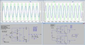
The Image below shows H3 for 3 sets of gain:
Gain = 50x for 0,1mV Carts, tested with 10Khz 1mV,
Gain = 20x for 0.25mV Carts, tested with 10KHz 2.5 mV and
Gain = 10x for 0.5mV Carts tested with a 10KHz 5 mV signal.
The Diff version is slightly better for larger values of Rs, but all H3 values are almost within the one digit ppm range, which is excellent and no reason to switch to a Diff version.
Apart from a possibly small noise penalty, the only reason for a Diff version would then be the incomparable CMRR performance.
Hans
Hans,
is my understanding of your setup correct for
as Duraglit gain is roughly Rload/Rsource, did you changed Rload accordingly to sweep Rsoure to maintain a constant gain e.g. 50x ?
If this is the case then e.g. single ended 50x gain at 1 R source had a Rload of approx 50 R while for a 10 R cart it has been set to 500 R. Then a huge H2 distortion of up to 40 dB higher for SE vs. Diff is well explainable as the current drive requirements for the 1R, x50 case would be 2.8 mA pp at a bias of 6.25 mA.
Does that acutally matter in the case it's floating? (dumb but honest question)You forgot that the output voltage is not referenced to GND any more
No, absolutely not
You forgot that the output voltage is not referenced to GND any more
Quite simple,
you just removed the ground from the output resistor. Common ground is now at the emitters for in and output! (this is what defines a 'common emitter' topology)
In post 664 about Fig. 4 in # 655:
but I did not introduce it.
Using the small drawing in post 669 I simply wanted to show that Fig. 4 in # 655 is
in fact an inverting negative feedback circuit. I did not want to imply that this simple
single gain stage has op-amp characteristics, but it has inverting and non-inverting
input and can be used with and without "feedback" (however here no "no feedback"
discussion in general intended). Until now this is trivial.
In post 674 also about Fig. 4 in # 655:
and get output - strongly correlated with the input signal.
is not "2*gm*R4", it is higher ..
I can not help, it seems not consistent to say "without R4 the AC open loop gain will be
large" (abbreviated) and in the next sentence "any load will change the gain significantly.
Therefore R4 can not simply be omitted".
...
In order to check some details I made a quick "Analog PSpice" breadboard set up of
Fig. 4 post 655 in Bob Pease style. This can be done in a few minutes (picture on
request). The circuit as seen has gain about -R4/R3 (70) as expected.
Now disconnecting R4 I see the full "open loop gain", about 350, surprisingly clean
by the way. Output voltage can exceed 1.5 volts pp until hard clipping occurs.
Next connecting R4 from output to ground you would expect a large drop in output
(gain also), but the circuit acts as with low output resistance and the drop is small.
Surprisingly the input impedance is going up at the same time, seemingly in part
compensating for the load (600 ohms generator output used).
Try it yourself (or do some sim). Any useful explanation for this is welcome. And no,
it was no oscillation ..
In this moment I fail to offer a full interpretation of this, but this is not simply two
grounded emitter circuits in parallel and a correct analysis is surely necessary.
This is true. Perhaps the term "open loop gain" can not be used adequately here,You need to define open-loop gain for this type of amplifier.
but I did not introduce it.
Using the small drawing in post 669 I simply wanted to show that Fig. 4 in # 655 is
in fact an inverting negative feedback circuit. I did not want to imply that this simple
single gain stage has op-amp characteristics, but it has inverting and non-inverting
input and can be used with and without "feedback" (however here no "no feedback"
discussion in general intended). Until now this is trivial.
In post 674 also about Fig. 4 in # 655:
I am not sure why you think so. The circuit powers up without R4, you can apply inputIn this simple transistor amp you can not take R4 out! ...
and get output - strongly correlated with the input signal.
I generally agree, but not exactly with this formula - or in other words: open loop gain... Without R4 (and without R5) the AC open loop gain is rc/re per transistor
(rc being the bjt intrinsic collector resistance and re being Vt/Ic). With rc in
the higher kOhm range, the gain will be large...
is not "2*gm*R4", it is higher ..
... But any load will change the gain significantly. Therefore R4 can not simply be omitted.
When doing a complete math analysis, R4 will be part of the feedback equations but also
part in the open loop gain calculation which is not the case if the open loop gain of the
amp (e.g. Opamp) is not dependent on the actual load the amp has to drive.
I can not help, it seems not consistent to say "without R4 the AC open loop gain will be
large" (abbreviated) and in the next sentence "any load will change the gain significantly.
Therefore R4 can not simply be omitted".
...
In order to check some details I made a quick "Analog PSpice" breadboard set up of
Fig. 4 post 655 in Bob Pease style. This can be done in a few minutes (picture on
request). The circuit as seen has gain about -R4/R3 (70) as expected.
Now disconnecting R4 I see the full "open loop gain", about 350, surprisingly clean
by the way. Output voltage can exceed 1.5 volts pp until hard clipping occurs.
Next connecting R4 from output to ground you would expect a large drop in output
(gain also), but the circuit acts as with low output resistance and the drop is small.
Surprisingly the input impedance is going up at the same time, seemingly in part
compensating for the load (600 ohms generator output used).
Try it yourself (or do some sim). Any useful explanation for this is welcome. And no,
it was no oscillation ..
In this moment I fail to offer a full interpretation of this, but this is not simply two
grounded emitter circuits in parallel and a correct analysis is surely necessary.
Nice work Hans.
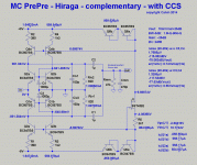
BTW I have updated the presentation with a few more graphs and MC amps
I just saw that you have further expanded your summary slide set.
but ...
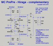
there is still one circuit missing: the Jean Hiraga 'Le pre pre' (if you google, you easily will find the original circuit). It's sindle ended similar to the simple Maxwell circuit but uses a current mirror and dual suppply to make the input DC voltage free (avoiding the huge input cap required otherwise).
My guess is, that an additional capacitor from the bases to ground will improve noise significantly.
ok - I will add it - probably not this week though. Did you see the Douglas Self design MC amp results ('Fermi')?
Hiraga - is it this one?
DIY Audio Projects Forum • Hiraga MC pre-preamp
Hiraga - is it this one?
DIY Audio Projects Forum • Hiraga MC pre-preamp
Last edited:
No, absolutely not
You forgot that the output voltage is not referenced to GND any more
Going from fig 3 to fig 4 uses a little poetic license. Take the simplest possible common emitter amplifier two resistors, one transistor, and current source to the rail. Making it complementary you get the transistors acting as each other's current source and an input that needs no AC coupling, the same feature set as the common base version.
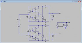
Here it is,Hans, please post a circuit of your Differential Duraglit.
Hans
Attachments
Common ground is now at the emitters for in and output! (this is what defines a 'common emitter' topology)
Common node of input signal and output signal is still on the bases, no matter where you will place GND symbol
I have no Idea what you mean.No, absolutely not
You forgot that the output voltage is not referenced to GND any more
The 47K and 150pF are the input of the following MM stage, where one side is connected to Gnd, you cannot simply take that away.
And the Cart is also connected to Gnd with one end, so ???
Put your model in LTSpice and see what it does.
Hans
Now disconnecting R4 I see the full "open loop gain", about 350, surprisingly clean by the way. Output voltage can exceed 1.5 volts pp until hard clipping occurs.
Next connecting R4 from output to ground you would expect a large drop in output (gain also), but the circuit acts as with low output resistance and the drop is small.
Well, an extraordinary result (in bold above) requires a careful analysis and explanation to be credible. Your experimental results contradicts the very basics (like regarding the output impedance of a common emitter stage, which is high, the gain of a common emitter stage, which is proportional to the load). Since the common emitter bipolar stage properties are known for many decades now, you need to explain your results, not the other way around.
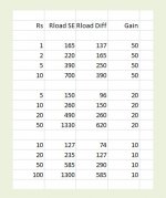
I did not sweep, but used discrete values where for each Rs a new Rload had to be found to give exactly the right gain.Hans,
is my understanding of your setup correct for
as Duraglit gain is roughly Rload/Rsource, did you changed Rload accordingly to sweep Rsoure to maintain a constant gain e.g. 50x ?
If this is the case then e.g. single ended 50x gain at 1 R source had a Rload of approx 50 R while for a 10 R cart it has been set to 500 R. Then a huge H2 distortion of up to 40 dB higher for SE vs. Diff is well explainable as the current drive requirements for the 1R, x50 case would be 2.8 mA pp at a bias of 6.25 mA.
See below a number of values used for Rs, Rload SE and Rload Diff.
I have also attached an image for Rs = 1R with a Gain of 50 for SE and Diff.
In case of the SE 428 uA pk is needed to drive R4 and for the Diff version 258 uA pk
So no way near the 2.8mA you expected.
Hans
P.S. The largest difference in THD of 91.7 between SE and Diff happened with Rs = 100 and a gain of 10
Attachments
Last edited:
Thanks
You are right - I simply forgot the input impedance of approx. 2 R when running the transistors at 6.25mA.
Theerfore you need the 165 R output resistor to get the 50x gain and not 50R.
Then the current drive requirement drops as well.
You are right - I simply forgot the input impedance of approx. 2 R when running the transistors at 6.25mA.
Theerfore you need the 165 R output resistor to get the 50x gain and not 50R.
Then the current drive requirement drops as well.
ok - I will add it - probably not this week though. Did you see the Douglas Self design MC amp results ('Fermi')?
Hiraga - is it this one?
DIY Audio Projects Forum • Hiraga MC pre-preamp
Yes, this is it. It got some cult status in certain audiophile circles.
As far as I know, this was also developed in the 80s a little bit later than the Leach/Lee common base complementary circuits.
And yes, have seen the 'Fermi'. Good but can be bettered (noise, overall distortion and current consumption) with less complexity.
Re my post 684 with " ..the circuit acts as with low output resistance and the drop is small." :
Yes, check it out in a couple of minutes, and as said "in this moment I fail to offer a
full interpretation of this". By the way I did not write it is simply common emitter.
Sorry, not enough time to work as an experimenter or even do a careful analysis, just
some spare breaks between work obligations, but in the meantime do we agree that
- gain of this fig. 4 is roughly -R4/R3;
- gain with R4 disconnected is "maximum" of what you can expect under these
circumstances (i e. without changing anything else) ?
If so in the next step please connect R4 from output to ground and see what happens.
Note : a 600 ohms source was used.
Well, an extraordinary result (in bold above) requires a careful analysis and explanation to be credible. Your experimental results contradicts the very basics (like regarding the output impedance of a common emitter stage, which is high, the gain of a common emitter stage, which is proportional to the load). Since the common emitter bipolar stage properties are known for many decades now, you need to explain your results, not the other way around.
Yes, check it out in a couple of minutes, and as said "in this moment I fail to offer a
full interpretation of this". By the way I did not write it is simply common emitter.
Sorry, not enough time to work as an experimenter or even do a careful analysis, just
some spare breaks between work obligations, but in the meantime do we agree that
- gain of this fig. 4 is roughly -R4/R3;
- gain with R4 disconnected is "maximum" of what you can expect under these
circumstances (i e. without changing anything else) ?
If so in the next step please connect R4 from output to ground and see what happens.
Note : a 600 ohms source was used.
Last edited:
Yes, this is it. It got some cult status in certain audiophile circles.
As far as I know, this was also developed in the 80s a little bit later than the Leach/Lee common base complementary circuits.
And yes, have seen the 'Fermi'. Good but can be bettered (noise, overall distortion and current consumption) with less complexity.
Yes, I played with it a bit today and it can be improved.
A lot of these simple circuits I noted do not have Ic optimized for lowest noise - I suspect with some tweaking a few tens of pico Volts/rt Hz reduction is possible.
So far I examined Richard's Duraglit mainly on noise, collector current and Rs.
Now I looked at the FR and noticed that depending on Rs and collector current, there can be a nasty bump below 10Hz when using 470uF caps.
The lower Rs, the larger the bump.
With Rs = 5 Ohm, it can already be as much as 7 dB, getting even larger for lower values.
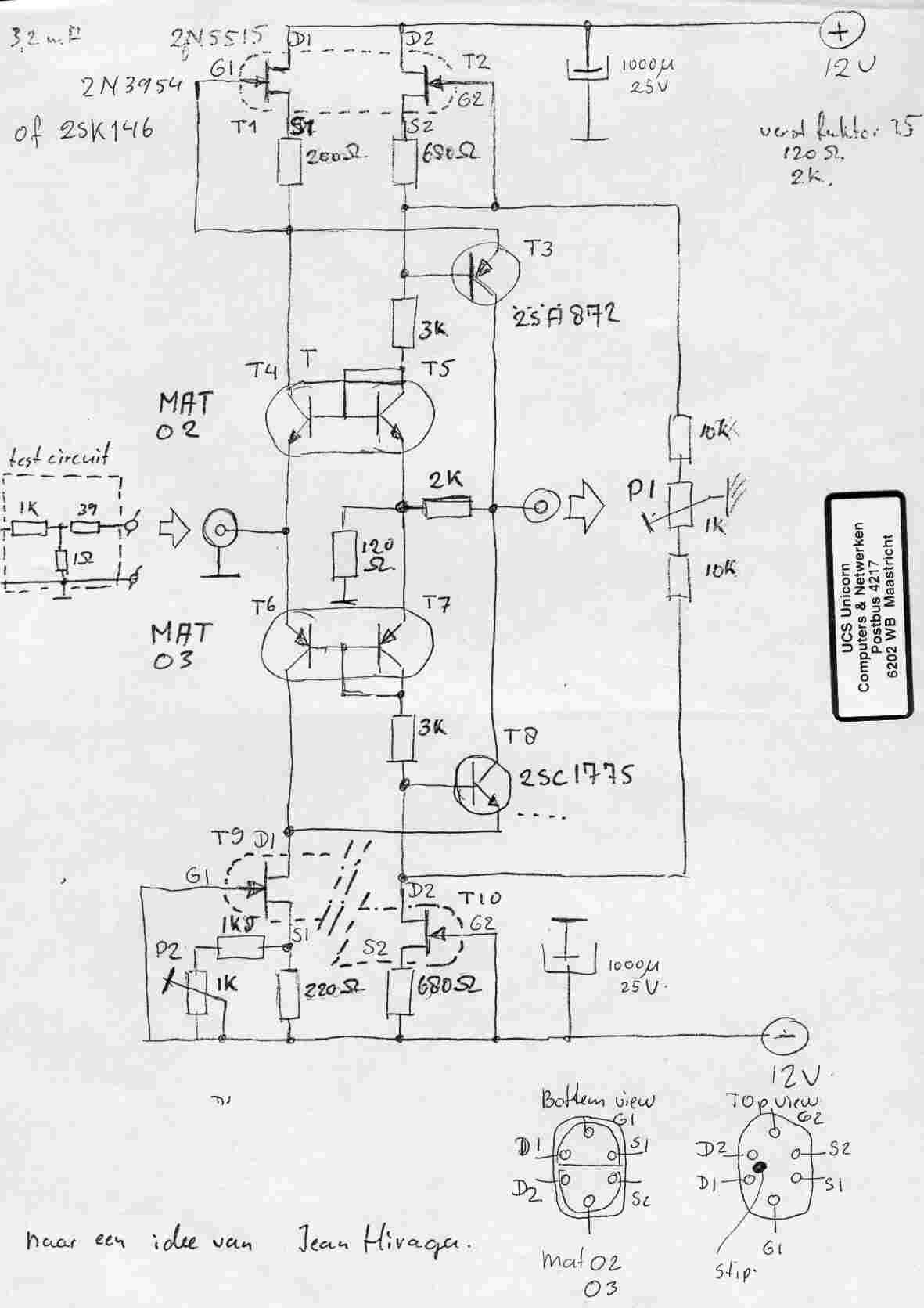
The remedy is to alter these caps into at least 5mF as can be seen in the image below where 0.5mF and 5mF are both used for Rs=5R and Rs=17.5R
Hans
Now I looked at the FR and noticed that depending on Rs and collector current, there can be a nasty bump below 10Hz when using 470uF caps.
The lower Rs, the larger the bump.
With Rs = 5 Ohm, it can already be as much as 7 dB, getting even larger for lower values.
The remedy is to alter these caps into at least 5mF as can be seen in the image below where 0.5mF and 5mF are both used for Rs=5R and Rs=17.5R
Hans
Attachments
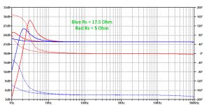
The remedy is to alter these caps into at least 5mF as can be seen in the image below where 0.5mF and 5mF are both used for Rs=5R and Rs=17.5R
I think Richard recognized this, the peaks can end up at record warp frequencies, very bad.
- Home
- Source & Line
- Analogue Source
- Richard Lee's Ultra low Noise MC Head Amp