Thanks Bill, sorry for the delay
Thanks for the WG calcs and OM help
Yea the smoothing was attempt to easily see the gross FR changes without the wigglys . The ribbon as a direct radiator is quite smooth however, about +-1.5 db all the way out with a very clean impulse.
So question, I see from WG graphs I posted that the entire FR does not evenly reduce off axis until about 45 degrees. it looks like the extreems are down a bit as we go off axis BUT it isn't until about 40 degrees or more that the whole curve is down. I see this effect BTW with ALL my WGs reguardless of size shape. Im not sure but I thought the intent is to have entire curve down somewhat evenly at each off axis point?
More data...
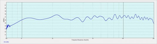
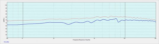
1st graph is ribbon freq response with trap, NO wave guide, and NO smoothing
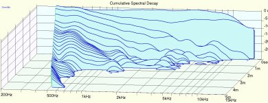
2nd is a close mic ( approx 1/2 inch) CSD direct drive , no trap, no Wave guide
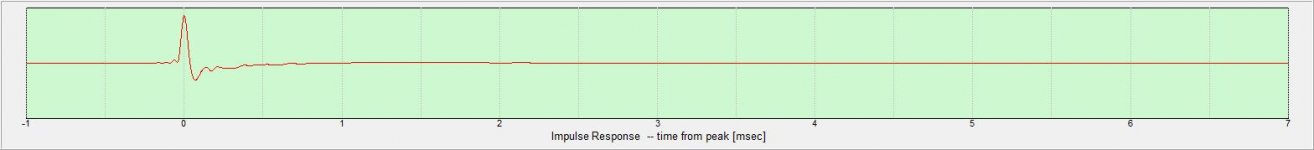
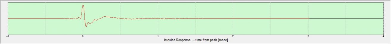
3rd is impulse close mic, no wave guide
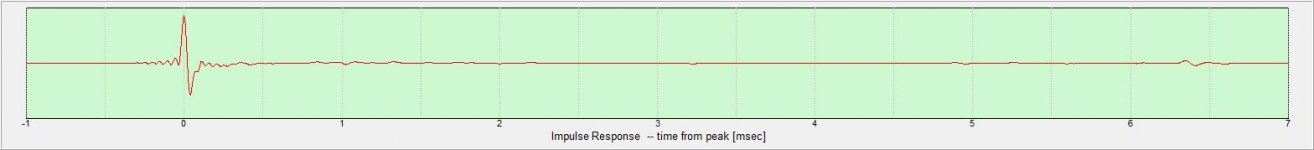
4th is impulse, at 1/2 meter, No wave guide
1st graph is ribbon freq response with trap, NO wave guide, and NO smoothing
2nd is a close mic ( approx 1/2 inch) CSD direct drive , no trap, no Wave guide
3rd is impulse close mic, no wave guide
4th is impulse, at 1/2 meter, No wave guide
Attachments
More data...
1st graph is ribbon freq response with trap, NO wave guide, and NO smoothing
2nd is a close mic ( approx 1/2 inch) CSD direct drive , no trap, no Wave guide
3rd is impulse close mic, no wave guide
4th is impulse, at 1/2 meter, No wave guide
1st: Gate on first measurement should be changed becouse it created ripple on frequency response, which type of gate and window limit (Hz, microseconds?) exactly did you use?
2st: Could you make the same measurement of random well-known dome tweeter? This CSD looks too good to be true. 🙂
3rd, 4rd is just like in point 2nd...
Wind..
1st I think it was 5 ms and was taken at about 1/2 meter. Can do again for sure . What settings would you like to see??
2nd I know what your saying on the "too good". BUT I assure you I spent many years refining that ribbon construction to get that smooth.My reference has been ultra low mass flat ribbon diaphragms similar to RAAL. I worked until my higher mass ribbon had a similar signature.
I can do two things
1- show same measure BUT with a standard corrugated ribbon of same size and mass and corrugation type.
2- the only dome I have laying around at the moment is a 3/4 inch silk from a pair of Polk speakers. It measures quite good BUT it sure doesnt sound like the ribbon. I plan to buy a couple of domes to compare. Any suggestions?
3rd- yep it is the best pulse I have ever gotten. When I first tryed this construction I was sure something was wrong with set up or measure system.
I am sorry, I have no spotted 1 dB magnitude grid scale... Looks more or less correctly if so.
Last edited:
I am sorry, I have no spotted 1 dB magnitude grid scale... Looks correctly if so.
Ah ok yea I was thinkin when I posted it I should call attention to the fact that it was a 1 dB scale.
At 5dB it looks crazy flat
More data...
1st graph is ribbon freq response with trap, NO wave guide, and NO smoothing
It needs an IRON supplement! (..for a waveguide.) 😉
..a bit more force in the gap should raise the response from about 3 kHz-up: giving you that additional "lift" that will be lowered somewhat in a shallow waveguide (..with a net response similar to the excellent result you have achieved here without a waveguide).
Ha yea shes catwalk material fo sho
Gona try some stronger magnets soon. BUT looks like only getting maybe 10% more flux with the best neos over the ones used here. My guess may not be nuff.
The same unit with 1/2 mass diaphragm does it easily BUT ribbons made that way simply do not hold up to a low crossover point.
Gona try some stronger magnets soon. BUT looks like only getting maybe 10% more flux with the best neos over the ones used here. My guess may not be nuff.
The same unit with 1/2 mass diaphragm does it easily BUT ribbons made that way simply do not hold up to a low crossover point.
Ha yea shes catwalk material fo sho
Gona try some stronger magnets soon. BUT looks like only getting maybe 10% more flux with the best neos over the ones used here. My guess may not be nuff..
-same magnets, just attach more iron to them. 😉
Per requests here is some other info...
1st - is a pulse for comparison from an inexpensive 3/4 inch silk dome. Same setup exactly as the close mic ribbon pulse in post 42 ( but admittedly done the next day). Perhaps not a good comparison but this is what I have at the moment.
Not shown here BUT very interesting to me is that this cheap dome had a very smooth freq response easily competing with the ribbon,low distortion also comparing well with ribbon, AND a CSD that looks even better than the ribbon!
However the Pulse reveals what my ears "see" clearly. The dome is NO match for the ribbon. In fact in listening tests even with a standard, higher distortion ribbon, the dome is not in same league.
In future I will get some better domes for compare,BUT again FR,CSD,and distortion simply do not tell the whole story in this case. At least as far as my ears are concerned, but the pulse is revealing. I suspect the domes nice FR and CSD are simply a well damped diaphragm that hides detail in its lossy construction.
2nd- is FR ( no smoothing) of Dynaplane ribbon ( red trace) and a typical corrugated ribbon construction of same size/mass/corrugation ( blue trace). Both ribbons mounted in same magnet structure and use same transformer
This to show what I find typically in simple corrugated ribbons ( see the sharp wiggle at 8.5 khz ) and some other deviations from smooth lower in freq.
The sharp wiggle at 8.5 Khz is the mass / spring resonance I see in All other "foil only", and to a lesser extent the laminated plastic backed ribbons, that are wider than about 10-12 mm.
That wiggle will have a long ugly tail in a CSD plot and can easily be moved around (lower or higher in freq.) depending on the size/shape of the corrugations.
To my ears this always sounds like added brightness an is fatiguing.
Less wide corrugated ribbons ( below about 10mm) will push this resonance out farther where its less noticed BUT now you have a very small ribbon with its more limited low freq use.
And to be sure we see some manufactures moving to "Flat" foil diaphragms that dont have this trait. However in my experience there are other issues with Flat and getting a small one to goto 1Khz results in diaphragm failure as well as poor control of some other resonances.Much of the work I have done is to eliminate that wiggle and others , in a wider ribbon diaphragm. The red trace tells that story
In my 1st ribbon patent I describe a construction where the corrugations are set within a certain range of angles rather than straight across. This construction increases the ribbons spring rate along its length without increasing mass and results in an improved centering force. This allowing use to lower freq. AND also eliminates that HF wiggle. However continued investigation of those designs has led to the present design we are showing data from in this thred
Attachments
Last edited:
I am sorry, I have no spotted 1 dB magnitude grid scale... Looks more or less correctly if so.
That is crazy smooth, really. And the ripple seems to be because of a reflection somewhere, not a ribbon resonance -- notice how the ripples get faster at high frequencies,-- that, on a log-frequency plot, usually indicates a discrete reflection off some object or edge. The ripple peaks seem to be about 1kHz apart, suggesting something maybe about a foot away (maybe the mic stand?) rather than something to do with the ribbon.
Either way, a dB isn't much in the real world of speakers in a room.
your right, good call , there is a structure close by.
At some point need to get to a bigger room but this is my work area for crude test for now. Mostly 1/2 meter tests with short gate.
Btw heres some more measurments ( 0-60 deg)with the larger wave guide ( cardboard and duct tape! Ha)with a roundover at the mouth. Hope to get to some more detailed tests soon.
Big Thanks to Bill for the help with my computer handicap Ha 😉
Attachments
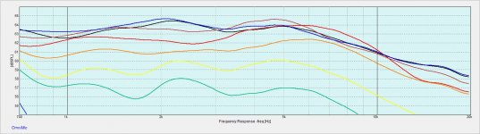

Still learning here and maybe not as big a deal as I think ?? , but I'm concerned with how the curves don't fall away between the 3 and 10 k region as much as it seems they should.
This is with a 15mm wide ribbon. WG profile at the throat? Narrow driver dispersion ignoring WG influence?
This is with a 15mm wide ribbon. WG profile at the throat? Narrow driver dispersion ignoring WG influence?
- Status
- Not open for further replies.
- Home
- Loudspeakers
- Multi-Way
- ribbons and wave guides