"This is all about dispersion of the driver, and how it is "squashed" relative to the resulting gain or loss at a particular angle."
The thing is this issue is happening no mater what size or angle the wave guide is built to.
Also when using the ribbon as direct radiator (no horn), we get the same roll off above 10k.
The thing is this issue is happening no mater what size or angle the wave guide is built to.
Also when using the ribbon as direct radiator (no horn), we get the same roll off above 10k.
Generating diffraction increases ripple in the summed-output (direct from ribbon interacting with diffraction). Less ripple = smoother decays.
The deeper the waveguide, the greater the diffraction from the waveguide. A deeper waveguide also tends provide a greater reaction with that diffraction.
Suggestion: try modeling with less deep waveguides (say, starting at half an inch in depth), and then scaling-"up" with increasing depth to note differences.
When I did the development work I wasnt using wave guides. All development was as a direct radiator. The ribbon is an unusual construction born out of years of development to clean up response And reduce distortion thats typical in small ribbons below about 1.5 Khz.
I actually have a couple of wave guides that are adjustable on the fly. You can take them from almost a tube to almost flat and watch the ripples in FR and you are right. However above 10k there is little change no matter the guides wall angles
Last edited:
hmm, higher mass ribbon causing pressure loss at higher freq.s?
Poor coupling to the waveguide? (..if there is little change above 10 kHz.)
Poor coupling to the waveguide? (..if there is little change above 10 kHz.)
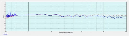
Well here is some more data...
blue is the ribbon in question with wave guide
red is same BUT with ribbon that is about 1/2 mass
I know from experience that in direct radiator use I would be EQing the red down to about where the blu is BUT not sure if I would do the same with a wave guided system as I have no experience there.
Anyway it looks like it was a driver diaphragm issue and not a wave guide issue??
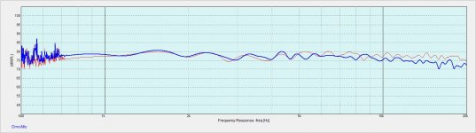
Attachments
Last edited:
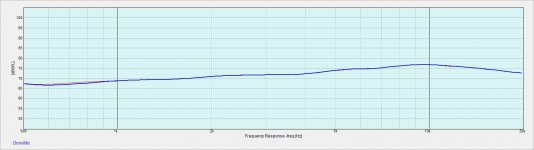
so in the above post I got about flat to 20K with a 3/4 inch wide ribbon by reducing diaphragm mass so I suppose I "forced " the extension using diaphragm mass. Not a desirable direction as the reliability when used to 1 KHz is not good.
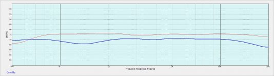
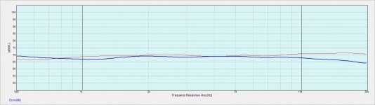
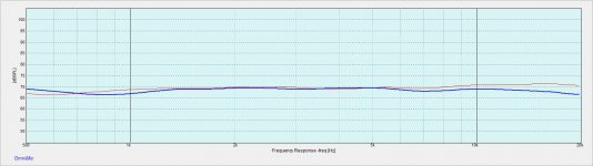
Moving on advice about diaphragm width, below is a comparison two ribbons using same wave guide ( yes throat was match to ribbons ) and same mass per unit area ribbons (the higher mass diaphragms).
The red is the 1/2 inch wide ribbon and blue is a 3/4 inch wide ribbon.
And lo the HF extension is achieved as predicted by the Sages.
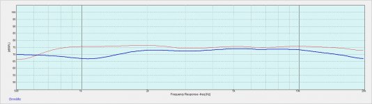
Attachments
Last edited:
Note: you could also increase magnetic field strength (in-the-gap) to increase upper freq. spl..
Last edited:
I have been playing around with waveguides on my ribbons in an effort to use them in higher sensitivity and more controlled directivity systems with larger woofers.
I admit to being uneducated in this area and busy enough now that I cannot devote much time to study. So I decided to build my curiosity by just throwing a bunch of crude “wave guides” ( all straight sided “cone shaped” , together (hot melt and thin wood) and just play.
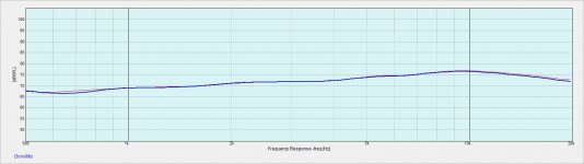
Yes I am quickly learning how critical small details can be here, however my first big impression is the roll off above about 10 kHz no matter what wave guide I use.
The wave guides can be tailored to get a response that is straight line linear down tilted slope from 1k out to 10k with 10k being -2db . From 10k to 20k the FR curve becomes slightly curved in shape and is down -5 db from 1k level.
This is an UN EQed response .
My question is this. I see this same effect (actually even more) on some other measurements of horn/CD driver arraignments that get some good press. So the question is, is this kind of response a real issue with systems using such controlled directivity??
I have not done listening tests yet and it will be a while before I do, so just curious if there is really a big issue here. In past designs using direct radiators with similar responses I always come away thinking that above 10k is not as big a deal as some are saying.
Anyway looking for wave guided wisdom……
You're not seeing a "rolloff above 10khz"
You're seeing that the horn reinforces the output below 10khz, but not above.
Apologies in advance if you already know this, but here's how this works:
A horn doesn't raise the efficiency of a loudspeaker, it just constrains the output into a narrower beam. IE, if you take a loudspeaker and you place it on a horn so that it's radiating into a beamwidth of ninety degrees, the output will go up because the same amount of energy is being concentrated into a narrow beam.

With a ribbon or a dome or a compression driver, there's a point where the wavelengths are smaller than the throat of the horn. For instance, if you're using a horn with a 1" throat, you're not going to see any gain above 13,500Hz. This is because 13,500HZ is one inch long, and the frequencies above 13,500HZ are smaller than the horn itself.
If you wanted to get 'horn gain' all the way to 20khz, you'd have to use a horn with a throat that's smaller than 0.675" in diameter. (20khz is 0.675" long.)
Does that make sense?
Also, check out my ribbon waveguides:
Ribbon Unity Horn
Last edited:
Thanks Patrick
Yes I now see this not just in theory but in practice
In post #24 we got good extension to 20k with the wider ( .75 inch ) ribbon in wave guide simply by lowering the mass of the ribbon enough to get the needed( desired?) levels past 10K.
In post #25 we see a comparison of two higher mass ribbons in wave guide but the red line is a 1/2 inch wide ribbon and the blue line is a 3/4 inch wide ribbon. Here we see the narrower higher mass ribbon achieving about the same extension as the wider, lower mass ribbon ( red line in post 24).
In the end I was able to reach a flat response out to 20k with the wave guide two ways. One by lowering ribbon mass and the other by reducing ribbon width.
Much of the work over the years has been to lower distortion, get a CSD thats noticeably cleaner and smoother to a lower frequency than is typical for a smaller ribbon , and increase reliability and motion control at lower freg. X over. No small task.
The wider ribbon was originally developed to be used as a direct radiator ( no wave guide). The 3/4 inch width as well as other design details were chosen in an effort to keep distortion in a rather small ribbon below 1% down to 1khz. That has been achieved and to my knowledge no other free swinging ribbon this small can do this.
The move to a wave guide was an attempt to use this ribbon with larger woofers and or higher sensitivity systems . And as Patrick and others ( Thanks to ALL!! ) have pointed out, ribbon width is important to maintaining good extension
Again thanks to ALL for the guidance. Wave guides are an area I have little knowledge or experience with and I believe I have been given a good start with the help of those here.
I would like to add however that Im not convinced just yet that this "flat" extension to 20K is as important as it seems.
Last edited:
Lowmass, could you show us dispersion characteristics of your newest invention? This is interesting what you are doing.
Lowmass, could you show us dispersion characteristics of your newest invention? This is interesting what you are doing.
Thanks Windforce
it is on the list for sure. I too want to know as it all seems a bit to good to be tru really.
Hopefully I can get something set up soon but will likely be end next week
Are u interested in the dispersion with or without wave guide?
Thanks Windforce
it is on the list for sure. I too want to know as it all seems a bit to good to be tru really.
Hopefully I can get something set up soon but will likely be end next week
Are u interested in the dispersion with or without wave guide?
Please check both cases at one measuring session so the results would be comparable to each other.
Not a ribbon but planar driver with and without a horn. Exact dimensions of the horn are not available, but there is kind of plug in the throat slot. Radian LT3 with horn, and many other planar designs too
LT3 Planar ribbon - Radian Audio
LT3 Planar ribbon - Radian Audio
An externally hosted image should be here but it was not working when we last tested it.
Not a ribbon but planar driver with and without a horn. Exact dimensions of the horn are not available, but there is kind of plug in the throat slot. Radian LT3 with horn, and many other planar designs too
LT3 Planar ribbon - Radian Audio
An externally hosted image should be here but it was not working when we last tested it.
YES I am seeing nice planers like this more and more. More cost effective and magnet efficient than a true ribbon BUT they do tend to have a higher Fs wich means a higher cross over.
That "plug" at the throat on these designs carries one of the 3 rows of magnets. I suppose it could have dual purpose?
Please check both cases at one measuring session so the results would be comparable to each other.
right of course , not sure why I even asked that . I think I mixed up thoughts from another thred.
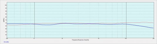
I took a quick peek last night out to 50 degrees off axis with WG and there may be an issue. The response levels are only reducing below about 3 khz up to about 30 degrees, then by 40 degrees the entire response is evenly reduced. Im not completely sure but that doesn't seem right.
These are very crude WGs so it looks like I may be in for schooling Ha.
Anyway I will try to get some data to post soon
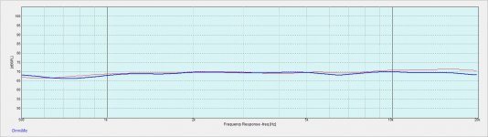
Ok so apology's in advance for the multiple FR graphs. I haven't learned yet how to do multi trace function.
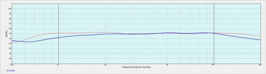
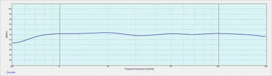
Here we see the Horiz. responses with Wave guide from 0 to 60 deg in 10 deg increments of the 15mm wide by 75mm long ribbon. WG is straight sided and not on a baffle.
WG dimensions are approx..
mouth 13 inches wide x 9 inches tall, 3.5 inches deep. Vert flare about 80 degrees, horiz flare about 120 deg. These dimensions chosen for their relatively flat response.
Attachments
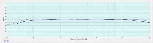
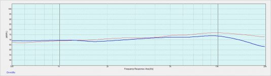
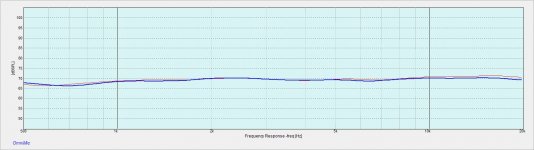
here we see same ribbons natural response NO WG and on large baffle 0 to 60 degrees in 10 deg steps
Attachments
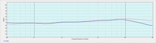


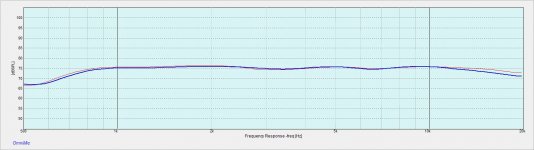
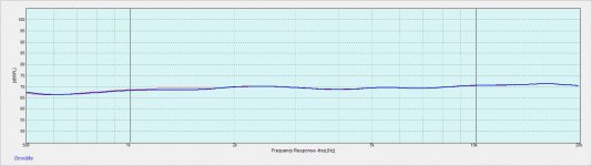
Here we see the same ribbon with a simple parallel trap circuit to deal with rise and hump, again 0-70 deg in 10 deg steps
Attachments

Ok so apology's in advance for the multiple FR graphs. I haven't learned yet how to do multi trace function.
There's really not a lot to learn other than what it's called -- first, click on "Files" then "Save FRD" and save the curve somewhere on your hard driver. Then click on the "Added Curves" menu at the top, and then on "Add".... goes pretty much naturally from there 😀
BTW, about waveguides ---- check your messages
also BTW -- in OmniMic, best to measure and save the files without any smoothing. You can always add smoothing when you add the curve to the screen, but you can't remove it after its saved with a file. Either your ribbon is very smooth or you have a lot of smoothing applied!
- Status
- Not open for further replies.
- Home
- Loudspeakers
- Multi-Way
- ribbons and wave guides