Not really. Signal is so low (~100uV) , that I have not found any difference in frequency response if I put 1uF, or 1nF.
Unless you have a really good battery model, then it may not make a difference in simulation. The battery model in my software isn't very sophisticated from what I can tell. All I have is the internal resistance to set, besides the value. 1,000uF @ a few volts is not a very big capacitor.
Sigh... see attached NIST study on battery noise. Please note that they also show the noise from a LM317 regulator, which is far more noisy than a battery. The quietest type is a Ni-Cad and next quietest appears to silver oxide.
Sorry, I misspoke. It's Ni-Cad as the quietest, not mercury.
Silver oxide is something like -193dBV/SQRTHz @ 10Hz to -199dBV/SQRTHz A 1kHz. Anyone got something more quiet than that? <g>
Last edited:
Hi,
You need to look at the bigger picture. No matter how "quiet" that battery it does not solve anything and I'll say as much as that it just won't work here.
I may be wrong but I doubt it.
I suggest to simply ground the cathode of the first stage and it will bias. No noise, no extra components and no idea why TS states it won't work. It should.
When Tina has calmed down, maybe a sim for what it's worth?
I think I've expressed sufficient reservations on the circuit already, so, to me at least the entire concept is pretty much "academic".
Ciao, 😉
Sigh... see attached NIST study on battery noise. Please note that they also show the noise from a LM317 regulator, which is far more noisy than a battery. The quietest type is a mercury (NLA?) and next quietest appears to silver oxide.
You need to look at the bigger picture. No matter how "quiet" that battery it does not solve anything and I'll say as much as that it just won't work here.
I may be wrong but I doubt it.
I suggest to simply ground the cathode of the first stage and it will bias. No noise, no extra components and no idea why TS states it won't work. It should.
When Tina has calmed down, maybe a sim for what it's worth?
I think I've expressed sufficient reservations on the circuit already, so, to me at least the entire concept is pretty much "academic".
Ciao, 😉
Hi,
You need to look at the bigger picture. No matter how "quiet" that battery it does not solve anything and I'll say as much as that it just won't work here.
I may be wrong but I doubt it.
I suggest to simply ground the cathode of the first stage and it will bias. No noise, no extra components and no idea why TS states it won't work. It should.
When Tina has calmed down, maybe a sim for what it's worth?
I think I've expressed sufficient reservations on the circuit already, so, to me at least the entire concept is pretty much "academic".
Ciao, 😉
I don't see any reasoning in your response. I don't see any evidence or anything except for your personal opinion, which is fine but it's just your opinion.
My opinion is that I see no reason why it won't work, and while the software may be optimistic about some things, I feel it's pointing me in the right direction for a low noise, low level gain stage.
I had to add a 1 ohm resistor to the circuit (I put it in the power supply) and then the noise simulation worked fine. It's off the charts. The S/N is so high that I don't even believe it. Clearly, flicker noise (1/f) noise from the tube, will dominate. I've discussed this circuit on my blog.
Can it be that because 6S45P was designed for RF they paid little attention to LF, that is why it is prone to flicker noise?
I suggest to simply ground the cathode of the first stage and it will bias. No noise, no extra components and no idea why TS states it won't work. It should.
I haven't used 6C45 much and not at all in a contact bias mode- is grid current through the transformer secondary going to be high enough to cause a rise in distortion?
Can it be that because 6S45P was designed for RF they paid little attention to LF, that is why it is prone to flicker noise?
All tubes are. See the Blencowe article linked in a few places here for some very illuminating data.
I've purchased the article. Very helpful. Unfortunately there is no data for 6s45p.
It also says, that active load (mu-follower in my case) topologies are not the best from noise perspective. Passive load are better. Though this statement is not supported by data.
As I see from the article, 6J52P is best from noise perspective.
In my younghood I had tape recorder that input tube was 6J32P. Using low noise penthodes was popular at hose time.
Anybody knows if 6J52P will be quieter than 6S45P-E ?
I am going to redesign the preamp to passive load with input tube 6N23P (ECC88) or 6S45P-E or 6J52P.
Any ideas?
The 6C45 won't be much different from the other high gm tubes shown. And the spread in noise should be an indication that, within reason, tube type "A" will not necessarily be quieter than tube type "B" even if the average A is quieter than the average B.
I think the high sensitivity region at 2-5kHz should be targeted when we set Ia for minimum noise. Or we should weight noise for human ear.
Here is another variant, where in accordance with Merlin Blencowe conclusion "For minimum noise the input stage should be passively loaded."
I've made input stage passively loaded. As well as paralleled for higher Gm.
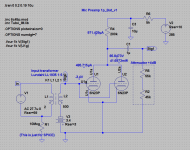
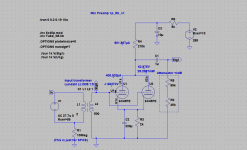
Here are schematics of the input stage.
One is traditional with bypassed Rk.
Another is with battery bias.
Noise and transient simulation is identical for both.
Which one do you like more?
I've made input stage passively loaded. As well as paralleled for higher Gm.
Here are schematics of the input stage.
One is traditional with bypassed Rk.
Another is with battery bias.
Noise and transient simulation is identical for both.
Which one do you like more?
Attachments

Last edited:
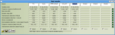
Modified existing preamp first stage. Instead of mu-follower I've made parallel SET. A little bit less noise.
It is in RMAA "p_6s45p" column.
A little bit more HF roll-off. A little bit more distortion, 2-nd harmonic.
previous column "v10_vol15" is previous mu-follower 1-st stage.
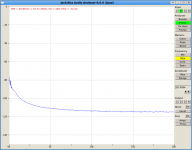
Second pic is how "no-input", open XLR signal looks like. Same is with 150R in input.
It is in RMAA "p_6s45p" column.
A little bit more HF roll-off. A little bit more distortion, 2-nd harmonic.
previous column "v10_vol15" is previous mu-follower 1-st stage.
Second pic is how "no-input", open XLR signal looks like. Same is with 150R in input.
Attachments
Hi,
That valve is similar to a D3a which is what SY uses in his "His Master's Noise" preamp.
In theory it should be low noise but short of actually measuring a ton of them it's hard to tell how noisy they are at LF.
I've measurements of a bunch of E83CCs showing them to be less noisy than E88CCs so there you go.
IME, to only way to find out is to build a test rig and select whichever valve you choose on all parameters that matter for the circuit you'll use them for.
Personally I'd replace the so called "passive" load with a decent CCS in the first stage. You're going to need all the gain you can get or the tiny signal will never be raised above the inevitable noise floor.
Agreed. I wonder to what extent this 1/f noise is actually audible in a properly designed stage. No idea what it sounds like...
Which begs the question, what is the average signal level presented at the grid of the first triode anyway? It is still well below that of a LOMC, isn't it?
Ciao, 😉
Anybody knows if 6J52P will be quieter than 6S45P-E ?
That valve is similar to a D3a which is what SY uses in his "His Master's Noise" preamp.
In theory it should be low noise but short of actually measuring a ton of them it's hard to tell how noisy they are at LF.
I've measurements of a bunch of E83CCs showing them to be less noisy than E88CCs so there you go.
IME, to only way to find out is to build a test rig and select whichever valve you choose on all parameters that matter for the circuit you'll use them for.
Personally I'd replace the so called "passive" load with a decent CCS in the first stage. You're going to need all the gain you can get or the tiny signal will never be raised above the inevitable noise floor.
I think the high sensitivity region at 2-5kHz should be targeted when we set Ia for minimum noise. Or we should weight noise for human ear.
Agreed. I wonder to what extent this 1/f noise is actually audible in a properly designed stage. No idea what it sounds like...
Which begs the question, what is the average signal level presented at the grid of the first triode anyway? It is still well below that of a LOMC, isn't it?
Ciao, 😉
Hi,
Wish I could find more data* about it but frame grid valves are by the nature of their construction less prone to this.
*Telefunken's Labor Buch band 2 touches this subject.
It's bound to cause some distortion but with a signal level 1/10 or less of even the lowest MC it should be obvious that this is "Mission Impossible" ?
Any measure taken to null the distortion caused by grid current is going to be met with a noise penalty, no doubt about that.
Hence my hint about it all being purely academic? Hence why I pointed out that the signal level has to be raised to useable levels first to at least overcome 1/f levels.
As much as I admire Merlin Blencowe's work and others such as Burkhard Vogels', but hey, wasn't this all horridly obvious from the start?
What is interesting though, but often ignored, is Blencowe's research on starved voltage circuits. Now that's interesting and that's something useful for anyone wanting to design a mic preamp.
Isn't it almost transistor like? It is, isn't it. Once again, nothing new under the sun and I think my little misunderstood MC stage proves it beyond doubt.
Anyhow, no matter how unscientifically broad minded one can be I still feel this entire project is impossible for you just can't expect a valve to amplify a signal to any useful level at its input that is well below its own intrinsic noise level.
I also don't buy this passive stage is less noisy stuff, in this case you need all the help you can get to lift the signal to useful levels, a mu-follower is a good start.
Ciao, 😉
All tubes are. See the Blencowe article linked in a few places here for some very illuminating data.
Wish I could find more data* about it but frame grid valves are by the nature of their construction less prone to this.
*Telefunken's Labor Buch band 2 touches this subject.
Quote:
Originally Posted by fdegrove View Post
I suggest to simply ground the cathode of the first stage and it will bias. No noise, no extra components and no idea why TS states it won't work. It should.
I haven't used 6C45 much and not at all in a contact bias mode- is grid current through the transformer secondary going to be high enough to cause a rise in distortion?
It's bound to cause some distortion but with a signal level 1/10 or less of even the lowest MC it should be obvious that this is "Mission Impossible" ?
Any measure taken to null the distortion caused by grid current is going to be met with a noise penalty, no doubt about that.
Hence my hint about it all being purely academic? Hence why I pointed out that the signal level has to be raised to useable levels first to at least overcome 1/f levels.
As much as I admire Merlin Blencowe's work and others such as Burkhard Vogels', but hey, wasn't this all horridly obvious from the start?
What is interesting though, but often ignored, is Blencowe's research on starved voltage circuits. Now that's interesting and that's something useful for anyone wanting to design a mic preamp.
Isn't it almost transistor like? It is, isn't it. Once again, nothing new under the sun and I think my little misunderstood MC stage proves it beyond doubt.
Anyhow, no matter how unscientifically broad minded one can be I still feel this entire project is impossible for you just can't expect a valve to amplify a signal to any useful level at its input that is well below its own intrinsic noise level.
I also don't buy this passive stage is less noisy stuff, in this case you need all the help you can get to lift the signal to useful levels, a mu-follower is a good start.
Ciao, 😉
to mm7
if you put in parallel the 6C45 you will get a great Cin that can modify the frequency answer.
I hope that you will not use the two trafos in input .
Regardin the 6J52P, you can look for E180F of, as said before, an EF184 NOS; the price is low and the quality is high.
In triode mode you will have, as I told you posts ago, a mu of 55 and a low Zp so the noise figure is acceptable.
You can supply this coonf with 100-120 Vdc, regulated by circuit with low Zout. Like TL783
Bye
Walter
Yes, that is why built mu-f first....
I also don't buy this passive stage is less noisy stuff, in this case you need all the help you can get to lift the signal to useful levels, a mu-follower is a good start.
...
Then I've build "passive load" with 2 paralleled 6S45P. It show a little bit less absolute noise, and a little bit higer SNR. But it is may be just because of 2 paralleled 6S45P. Anyway it gives slightly better result.
Then I've done same with 2 paralleled 6N23P (ECC88), but signal was so low that I could not take measures. May be something was mis-soldered. I gave up for the day.
So far 2 paralleled 6S45P-E passive load stage shows best result.
I did not play with lowering heater voltage/current yet.
Another wild idea to use 2 separate heater PSUs. One for upper tube heaters elevated to 50v above their cathodes. Another for lower tubes also elevated to 50v above their cathodes.
Currently I use cheap switch mode 12V PSU elevated to 100V so upper tube heaters are negatively "elevated" to -100V.
Regarding starved mode. Starved mode also decreases gain. So in result S/N is same. According to simulations. I do not know how it is in reality. Does anyone know?
Yes, that is why built mu-f first.
Then I've build "passive load" with 2 paralleled 6S45P. It show a little bit less absolute noise, and a little bit higer SNR. But it is may be just because of 2 paralleled 6S45P. Anyway it gives slightly better result.
Then I've done same with 2 paralleled 6N23P (ECC88), but signal was so low that I could not take measures. May be something was mis-soldered. I gave up for the day.
So far 2 paralleled 6S45P-E passive load stage shows best result.
I did not play with lowering heater voltage/current yet.
Regarding starved mode. Starved mode also decreases gain. So in result S/N is same. According to simulations. I do not know how it is in reality. Does anyone know?
Starved mode also increases distortion, depending on tube type.
DC heater supply is also an obvious choice for lowest noise.
According to conversations with David at Cine Mag transformers, the greatest S/N is achieved with a plate choke load. He stated to me in a private email that their oem's are reporting this fact.
The problem with using resistors in the plate circuit is that the noise goes up with larger ones, depending on voltage and current of course.
I've discussed some aspects of this circuit on my blog.
If you use battery bias, you must bypass it with a large capacitor. Batteries are non-linear with frequency, as are LED's.
Yes I see minor HF rolloff.to mm7
if you put in parallel the 6C45 you will get a great Cin that can modify the frequency answer.
I just do not have two trafos 🙂to mm7
I hope that you will not use the two trafos in input .
Thanks Walter. It looks I should try it. My hope is they (EF164/6J52P) were designed for low noise sound and TV amps while 6S45P was designed for radars, possibly with little attention to sound (LF) diapason, just my suggestion.to mm7
Regardin the 6J52P, you can look for E180F of, as said before, an EF184 NOS; the price is low and the quality is high.
In triode mode you will have, as I told you posts ago, a mu of 55 and a low Zp so the noise figure is acceptable.
You can supply this coonf with 100-120 Vdc, regulated by circuit with low Zout. Like TL783
So may be EF164/6J52P will make less noise.
Batteries are non-linear with frequency, as are LED's.
Data? I haven't tested batteries, but I've certainly tested LEDs, and they don't have any significant change in their impedance up to 85kHz (my measurement limit).
The problem with using resistors in the plate circuit is that the noise goes up with larger ones, depending on voltage and current of course.
Not necessarily. The voltage divider with the tube's effective plate resistance also decreases. Voltage noise increases as sqrtR, voltage divider decreases noise as R.
Starved mode also increases distortion, depending on tube type.
I wouldn't give that as a blanket rule. See, for example, my data given at http://www.diyaudio.com/forums/tube...simple-el34-push-pull-design.html#post1669904 .
- Status
- Not open for further replies.
- Home
- Amplifiers
- Tubes / Valves
- Ribbon Microphone Preamp