Hi,
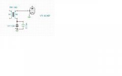
Cathode grounded. Grid biased by battery.
If the cathode resistor is the source of the noise then surely a lower value would produce less noise?
I saw you used a smaller value resistor of 100R in a previous version. Noisier or less so?
With such a small input signal you could just as well ground the cathode. With the top triode as acting as a CCS it will selfbias sufficiently.
Ciao, 😉
Battery? I am afraid that battery is a questionable conductor of variable current. Batteries are not designed to conduct any signal in sound diapason. Capacitors are.
Cathode grounded. Grid biased by battery.
If the cathode resistor is the source of the noise then surely a lower value would produce less noise?
I saw you used a smaller value resistor of 100R in a previous version. Noisier or less so?
With such a small input signal you could just as well ground the cathode. With the top triode as acting as a CCS it will selfbias sufficiently.
Ciao, 😉
Yes 1:37 SUT should bring ribbon signal to magnitude of dynamic mics. Not exactly same, but a bit lower. It also depends on other factors like thickness of ribbon, its size, and width of baffles that are placed at ribbon sides. The wider baffles the stronger signal, but HF limit is lower. I've made baffles quite narrow to increase HF up to 20kHz, so sensitivity is 1.1mV/Pa according to calculations. (I do not have devices to measure it in reality.)
Yes, but in this case a cap or bigger R in grid is required to keep bias voltage. This R will result 1.4uV of noise on first stage output. While existing schematic gives 240nV.Hi,
Cathode grounded. Grid biased by battery.
Simulated, does not work.If the cathode resistor is the source of the noise then surely a lower value would produce less noise?
I saw you used a smaller value resistor of 100R in a previous version. Noisier or less so?
With such a small input signal you could just as well ground the cathode. With the top triode as acting as a CCS it will selfbias sufficiently.
I feel that it does not make sense to change existing schematic because this noise is produced not by passive components but by tubes themselves.
I'll better will try to reduce plate current and/or voltage, and may be reduce heater.
Hi,
It should though.
In which case the only option to go about is to parallel tubes jut like I did with the MC stage. it should reduce tube noise by some 3dB.
Either that or improving the source's efficiency: thinner foil, higher step-up ratio xformers if possible and so on.
And since you like the Thirties:
http://dalmura.com.au/projects/A%20study%20of%20noise%20in%20vacuum%20tubes%20and%20attached%20circuits.pdf
Reducing heater voltage usually helps reducing noise, Reducing current through the tube affects transconductance so you'll need to find the optimum balance there.
Ciao, 😉
Simulated, does not work.
It should though.
I feel that it does not make sense to change existing schematic because this noise is produced not by passive components but by tubes themselves.
In which case the only option to go about is to parallel tubes jut like I did with the MC stage. it should reduce tube noise by some 3dB.
Either that or improving the source's efficiency: thinner foil, higher step-up ratio xformers if possible and so on.
And since you like the Thirties:
http://dalmura.com.au/projects/A%20study%20of%20noise%20in%20vacuum%20tubes%20and%20attached%20circuits.pdf
I'll better will try to reduce plate current and/or voltage, and may be reduce heater.
Reducing heater voltage usually helps reducing noise, Reducing current through the tube affects transconductance so you'll need to find the optimum balance there.
Ciao, 😉
Last edited:
Battery? I am afraid that battery is a questionable conductor of variable current. Batteries are not designed to conduct any signal in sound diapason. Capacitors are.
You'd have to bypass the battery with a large capacitor to achieve acceptable results, but then you have to deal with replacing batteries and the fact that they change voltage as they discharge (some are better than others about that). I would not use one in the cathode circuit. I have a technique to use a battery where the battery doesn't have to handle any significant current though. (Fred already said it) It would probably be very quiet...
Attachments
Last edited:
Ha, the circuit I posted is apparently very confusing to Tina (my spice simulator) after I added a plate load and supply voltage. Noise is zero.... input, output, and total... ZERO! hahaha. S/N is -100dB (it should be +140dB or more).... something is very strange but hey, it's probably the cat's meow in low noise.
That's the first time I got Tina confused. She must be really annoyed with me right now.
The battery is a standard silver oxide coin type.
It's cool enough that it makes me want to build it just to see what's up. I don't think I have an application for it though.
That's the first time I got Tina confused. She must be really annoyed with me right now.
The battery is a standard silver oxide coin type.
It's cool enough that it makes me want to build it just to see what's up. I don't think I have an application for it though.
Last edited:
You'd have to bypass the battery with a large capacitor to achieve acceptable results, but then you have to deal with replacing batteries and the fact that they change voltage as they discharge (some are better than others about that). I would not use one in the cathode circuit. I have a technique to use a battery where the battery doesn't have to handle any significant current though. (Fred already said it) It would probably be very quiet...
Fred's initial idea was to remove capacitor, because it brings nonlinearity. Here we again at corner one. Plus we get inconveniences with batteries.
Is it really 1mF = 1000uF cap on your schema? Why so big?
LTSpice is OK. Though it does not have batteries. I just put a generic V source.Ha, the circuit I posted is apparently very confusing to Tina (my spice simulator) ...
Hi,
What's the purpose of that cap anyway?
That's entirely different. The cathode bypass cap(s) interact with the AC signal on the cathode shunting it to ground.(Err...if Fred is me ten it's actually Frank, not Fred😀)
Further to this:
It should though.
Ciao, 😉
Is it really 1mF = 1000uF cap on your schema? Why so big?
What's the purpose of that cap anyway?
Fred's initial idea was to remove capacitor, because it brings nonlinearity.
That's entirely different. The cathode bypass cap(s) interact with the AC signal on the cathode shunting it to ground.(Err...if Fred is me ten it's actually Frank, not Fred😀)
Further to this:
Simulated, does not work.
It should though.
Ciao, 😉
Fred's initial idea was to remove capacitor, because it brings nonlinearity. Here we again at corner one. Plus we get inconveniences with batteries.
Is it really 1mF = 1000uF cap on your schema? Why so big?
Man, it's so obvious....
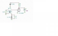
The transformer secondary tail end has to be at AC ground potential. The battery has internal resistance (about 1 ohm or so - I'm not sure of this) and really strange frequency response. Therefore, it has to be bypassed with a large capacitor in order to insure that the tail end of the transformer secondary stays at AC ground for all frequencies. You must separate the AC from the DC. That's what the capacitor does.
I didn't show you the complete schematic so obviously it does not work. I've attached a complete schematic. It works absolutely fine right now. It's outstanding, actually.
Why are you worried about a battery here? Don't you realize that the grid current for this tube is going to stay so low that the battery will last for a year or more (probably). What's the grid current? a few pico amps? Nothing to worry about!
Attachments
Last edited:
Hi,
You don't have to involve the xformer secondary and there's no need to worry about the battery's FR either. Just move it to the grid of the tube and leave the secondary grounded.
The voltage of a fresh battery will likely be too high though. No idea in what voltages these coin batteries are available but -2V is too high.
It'll likely last its normal shelf life.
Ciao, 😉
The transformer secondary tail end has to be at AC ground potential. The battery has internal resistance (about 1 ohm or so) and really strange frequency response. Therefore, it has to be bypassed with a large capacitor in order to insure that the tail end of the transformer secondary stays at AC ground for all frequencies. You must separate the AC from the DC. That's what the capacitor does.
You don't have to involve the xformer secondary and there's no need to worry about the battery's FR either. Just move it to the grid of the tube and leave the secondary grounded.
The voltage of a fresh battery will likely be too high though. No idea in what voltages these coin batteries are available but -2V is too high.
Don't you realize that the grid current for this tube is going to stay so low that the battery will last for a year or more (probably). What's the grid current?
It'll likely last its normal shelf life.
Ciao, 😉
Hi,
You don't have to involve the xformer secondary and there's no need to worry about the battery's FR either. Just move it to the grid of the tube and leave the secondary grounded.
Ciao, 😉
Really? Can you show me what you mean because I don't understand? Do you mean to put the battery in series between the transformer secondary and the grid?
Why would you assume that the battery is going to be linear in this application? Do you have evidence that it would be? I can't find anything on that.
Attachments

Last edited:
Hi,
Not in series but in //. Just connect the negative terminal of the battery to the grid and the positive one to ground.
The negative terminal needs a high value resistor in series though so that may well be a source of noise here that you'd like to avoid. Never measured it though, may well turn out to be totally benign.
Ciao, 😉
Hi,
Not in series but in //. Just connect the negative terminal of the battery to the grid and the positive one to ground.
The negative terminal needs a high value resistor in series though so that may well be a source of noise here that you'd like to avoid. Never measured it though, may well turn out to be totally benign.
Ciao, 😉
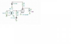
OK, so what do you think the grid voltage is for this circuit?
Do you really think it's going to 1.55V????? huh?
It's some 6mV because of the low resistance of the transformer secondary. Therefore, you need a capacitor between the 100k resistor and the transformer secondary... duh.
Attachments
Hi,
Which you now put between the secondary winding and ground. (Which in turn may also lead to hum problems)
Nonetheless, the battery bias isn't the best way to tackle the problem.
Your initial idea may work better but I have my doubts about lifting the ground of the xformer at DC levels.
Ciao, 😉
Therefore, you need a capacitor between the 100k resistor and the transformer secondary... duh.
Which you now put between the secondary winding and ground. (Which in turn may also lead to hum problems)
Nonetheless, the battery bias isn't the best way to tackle the problem.
Your initial idea may work better but I have my doubts about lifting the ground of the xformer at DC levels.
Ciao, 😉
Not really. Signal is so low (~100uV) , that I have not found any difference in frequency response if I put 1uF, or 1nF.Is it really 1mF = 1000uF cap on your schema? Why so big? Man, it's so obvious....
Yes, this is the quietest solution in simulation. I'll definitely try this.I didn't show you the complete schematic so obviously it does not work. I've attached a complete schematic. It works absolutely fine right now. It's outstanding, actually.
Any advises on battery type? NiMH, Li, Silver?
My apologies, Frank.fdegrove said:if Fred is me ten it's actually Frank, not Fred
Hi,
You mean the cathode R bypass caps?
If so then that shows my point exactly.
Besides that, I think I pointed out earlier as well, and I'm well aware that you want this mic pre to be as wideband as possible, there's no point of having a 1microF cap to the grid of the top tubes either. With the 150K grid leak bootstrapped it looks like an input impedance of several mega ohm so all in all a 100nf suffices.
Smaller caps are faster in charging/discharging and it will also increase overall stability.
Batteries can be noisy as well. This one of the reasons I think it may not be the best idea here.
I suspect the coin types (Cr20xxx) to be the "quieter" types. Not sure about this though.
Even so, that leaves the grounding of the secondary winding.
No probs. 😎
Ciao, 😉
Not really. Signal is so low (~100uV) , that I have not found any difference in frequency response if I put 1uF, or 1nF.
You mean the cathode R bypass caps?
If so then that shows my point exactly.
Besides that, I think I pointed out earlier as well, and I'm well aware that you want this mic pre to be as wideband as possible, there's no point of having a 1microF cap to the grid of the top tubes either. With the 150K grid leak bootstrapped it looks like an input impedance of several mega ohm so all in all a 100nf suffices.
Smaller caps are faster in charging/discharging and it will also increase overall stability.
Yes, this is the quietest solution in simulation. I'll definitely try this.
Any advises on battery type? NiMH, Li, Silver?
Batteries can be noisy as well. This one of the reasons I think it may not be the best idea here.
I suspect the coin types (Cr20xxx) to be the "quieter" types. Not sure about this though.
Even so, that leaves the grounding of the secondary winding.
My apologies, Frank.
No probs. 😎
Ciao, 😉
Batteries can be noisy as well. This one of the reasons I think it may not be the best idea here.
I suspect the coin types (Cr20xxx) to be the "quieter" types. Not sure about this though.
Even so, that leaves the grounding of the secondary winding.
Ciao, 😉
Sigh... see attached NIST study on battery noise. Please note that they also show the noise from a LM317 regulator, which is far more noisy than a battery. The quietest type is a mercury (NLA?) and next quietest appears to silver oxide.
Attachments
Yes, this is the quietest solution in simulation. I'll definitely try this.
Any advises on battery type? NiMH, Li, Silver?
Here is one good type. Note the discharge characteristics.
Attachments
- Status
- Not open for further replies.
- Home
- Amplifiers
- Tubes / Valves
- Ribbon Microphone Preamp