That time constant causes -3dB at around 2Hz. If that frequency is made too low however,
there could be low frequency instability, depending on the circuit and power supply.
A tube feedback RIAA circuit will never have as good eq as a solid state circuit can, because of
the limited available excess gain at low frequencies.
there could be low frequency instability, depending on the circuit and power supply.
A tube feedback RIAA circuit will never have as good eq as a solid state circuit can, because of
the limited available excess gain at low frequencies.
Last edited:
well .. if 0.15uF cut at that frequency it is useless to increase it to 0.22 / 0.33 / 0.47uF, am I right?
It is already as low as it seems to me, outside the audio band.
However, I have noticed that in other AR schemes .. identical schemes .. that cap is even higher in value up to 0.47uf.
I don't know what improvement it can give then ..
It is already as low as it seems to me, outside the audio band.
However, I have noticed that in other AR schemes .. identical schemes .. that cap is even higher in value up to 0.47uf.
I don't know what improvement it can give then ..
...but, what are the components of the air network that determine the equalization at very low frequencies (resistance and / or capacitor)?
Can you kindly point them out to me?

Thanks
Can you kindly point them out to me?
Thanks
The theoretical RIAA network values for an infinite gain circuit will not give perfect eq in a tube RIAA circuit,
due to the limited excess gain at low frequencies. For a tube global feedback RIAA to have midband gain
of 40dB, the gain at low frequencies must be 60dB (x1000). For this gain to be accurate, the excess gain would
have to be x10 for 1dB accuracy. This means that the open loop gain of the circuit would have to be x10,000.
This amount of gain will not be available in a two stage tube circuit.
Some resort to adjusting the ideal component values in an attempt to compensate for the lack of excess gain,
but this cannot give the same results as the correct amount of excess gain. All the time constants interact
in this circuit.
Last edited:
I understand the concept.
Thanks for explaining it to me.
According to my accounts, if I was not wrong (I don't think so) the situation is this:
20Hz: -2,42dB
1Khz: 0
20Khz: +0,45dB
..respect the "official" riaa curve.
Should I therefore consider that -2.42dB "normal"?😱
Thanks for explaining it to me.
According to my accounts, if I was not wrong (I don't think so) the situation is this:
20Hz: -2,42dB
1Khz: 0
20Khz: +0,45dB
..respect the "official" riaa curve.
Should I therefore consider that -2.42dB "normal"?😱
Last edited:
20Hz is not audible in most music systems.
What is your error at 50Hz?
If you are 0.5dB at 100Hz and 1.5dB at 50Hz, that is very very good.
What is your error at 50Hz?
If you are 0.5dB at 100Hz and 1.5dB at 50Hz, that is very very good.
Should I therefore consider that -2.42dB "normal"?😱
Yes, for a global negative feedback tube RIAA circuit. A passive tube RIAA can do better in this respect,
since it does not have that particular problem.
20Hz is not audible in most music systems.
What is your error at 50Hz?
If you are 0.5dB at 100Hz and 1.5dB at 50Hz, that is very very good.
I have measured and calculated now.
If I haven't made a mistake:
50Hz: -1.78dB
100Hz: -1.13dB
It is not very good! 🙁
Increase the 1.82Meg resistor to 2Meg or 3M, re-measure.
However this IS the problem with basic NFB tube preamps: not enough open-loop gain to have clean predictable bass. Passive EQ can be the right EQ but the overall gain will change with tube replacement or aging.
Frankly, 1dB @ 100Hz and 2dB @ 50Hz is much better than any speaker/room response.
However this IS the problem with basic NFB tube preamps: not enough open-loop gain to have clean predictable bass. Passive EQ can be the right EQ but the overall gain will change with tube replacement or aging.
Frankly, 1dB @ 100Hz and 2dB @ 50Hz is much better than any speaker/room response.
Hi PRR, The values I use in the riaa network, for a pair of components, are slightly different from the schematic. A friend from the forum, a long time ago, calculated them for me. Unfortunately I can no longer communicate with him.
Your advice to increase the resistor up to 3Mega and measure is always valid in this case too, right?
Perhaps, considering that I am starting from 1M current, I can increase it up to 2M and no more...i suppose.
Will I lose gain by increasing the value of that resistor?
Thanks for the advice and your patience.
I enclose the complete current scheme.
Hi TasoTaso & All
I just saw this and it was quite a good read. I use my Audio Precision System and use the reverse RIAA on the generator and the graph then is FLAT FREQUENCY RESPONSE.
Duke
I just saw this and it was quite a good read. I use my Audio Precision System and use the reverse RIAA on the generator and the graph then is FLAT FREQUENCY RESPONSE.
Duke
Hi!
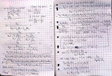
I tried to calculate the exact values for the perfect match to the RIAA curve.
It is a bit long, so I made it on paper sheets, I took a photo of it.
I included also the 3.18us null, because it was possible. But can somebody check the math, because I maight make some mistake. I am not good at LTspice, but if somebody have time to check it it would be the best. I assumed infinite open loop gain, so it is the week point, but otherwise it is not possible to calculate it.
So Rk is the kathode resistor, R1C1 and R2C2 is in my drawing not in the circuit above.
First you have to set the Rk, then:
R1=Rk x 17.675139
R2=Rk x 217.173861
R1C1=75us
R2C2=3180us
The low frequency gain is G=235.849 at infinite open loop gain.
With ECC83 u=100 the gain is G=A/(1+ßA) =230.41
Attachments

Here are some verified RIAA calculations.
Website of Wayne Stegall - Phono Equalization Calculations
Website of Wayne Stegall - Phono Equalization Calculations
Hi,
passive inverse RIAA filters are old-school. A loss-less solution is desirable as I showed here:
https://www.sowter.co.uk/pdf/LCR-RIAA Ahlswede.pdf
A simple sweep with this iRIAA "filter" by using a tool like REW is everything that is needed and the mathematical correct solution.
Btw, the so called Neuman constant is a myth and was never used in that way in any cutting amplifier.
to docali
Hi Bernd ( we spoke in another forum)
I have mentioned your paper on my first article on LCR in Audioreview magazine in Italy.
I used the 1280 stuff from Sowter.
Now with the help of an engineer/mathematic that is working in Germany (he is italian) will be presented a different approach to RIAA with inductors.
Always on Audioreview magazine
Walter
Hi Walter,
I am in doubt that there will be new approaches than the already known LCR, LR or Rx Corrector with specific defined stray inductance of transformers but I am of course open to extend my mind 😉
Maybe negative feedback which would be not my cup of tea.
If you have a pre-print I would appreciate to take a look into your topic.
Hi
I have seen the first foil, but I am not a mathematic man!! 🙂
It is a different approach, said to me.
I think within one month we can have something more complete with an excel (I hope)
No feedback on circuit in every case!
Walter
Walter
I have seen the first foil, but I am not a mathematic man!! 🙂
It is a different approach, said to me.
I think within one month we can have something more complete with an excel (I hope)
No feedback on circuit in every case!
Walter
Walter
Hi Walter,
the Excel is existing since many years already thanks to the great work of ClausD:
https://www.diyaudio.com/forums/analogue-source/227736-riaa-lcr-mythos-4.html#post3505921
ClausD's whitepaper is the most comprehensive and best mathematical work I know about LCR on base of theoretically perfect inductors and he provided a spread sheet calculator. imho everything about LCRs has been already told. But I am very curious about your progress.
- Home
- Source & Line
- Analogue Source
- RIAA inverse circuit for analysis and Testing PrePhono