I don't understand your sketch...
1.) If you want to test this iRIAA with 562R generator, you must use
1960-562= 1398R as first serial resistor (R5);
2.) If you want test the above iRIAA (R5= 1398) with generator (164R impedance), you must use 562-164= 398R resistor serial with this generator;
3.) If you want test the above iRIAA (R5= 1398) with generator (50R impedance), you must use 562-50= 512R resistor serial with this generator;
In all cases the generator impedance + series resistance + R5 equal 1960R.
Thanks, yes, today I did the right calculations and they are like yours.
Perfect! Thank you again.
My drawing is not important.
Today I found the solution of combining resistors and switch / diverter that allows me to have only 2 input connectors (right and left) with 3 different types of generators (different output impedances), saving money!
Bye 😀
Perfect! Thank you again.
My drawing is not important.
Today I found the solution of combining resistors and switch / diverter that allows me to have only 2 input connectors (right and left) with 3 different types of generators (different output impedances), saving money!
Bye 😀
That is the best way to do it, with a constant input level converted to the equivalent of the cartridge's output.
Otherwise you would have to vary the input level for each data point, to get a constant output level.
And you can use a square wave input, and see directly the evenness of the response and phase shift.
Also you can play a line level source (like master tapes) through a stereo IRIAA and do listening tests, very useful.
That's the only way to do a phono stage bypass test (JGH did this).
Last edited:
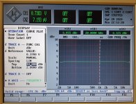
Hi, I finished the iRIAA.
I made these measurements using the Wien generator (analog, no display, big knob!)
Basically I detect, at these three precise frequencies, these attenuations:
at 20Hz an attenuation of -58.44dB
at 1000Hz an attenuation of -39.66dB
at 20.000Hz an attenuation of -20.22dB
I also made these measurements, at some frequency values taken from the spice simulation (I didn't do the simulation myself, Taken from the document explaining how to make the circuit).
First Column: Freq. in Hz
Second Column: Input in mV
Third Column: Output in mV
Fourth Column: dB I calculated (Decibels to Voltage Gain and Loss convert calculation conversion amplification amplifier electronics - sengpielaudio Sengpiel Berlin)
Fifth Column: The value ("should dB") in dB present on the spice simulation ... (I don't know if it was necessary to have it under my eyes, but I wrote it), that is what "should" be, net of the - 40dB that the circuit constantly applies.


Considering that the circuit, besides "equalizing", attenuates by 40db ...... always and constantly, it should be ok, right?
I mean at 1Khz I should have, in theory, -40dB, at 20Hz -60dB and at 20.000Hz -20dB, right?
I notice that, at 20Hz, I have a bit high error, 1.56dB.
The error is big at very low frequency probably because both the generator and the oscilloscope (USB) are a bit at the bandwidth limit, I suppose.
Is this a correct consideration?
There are also 3 "things" that can introduce errors, circuit, oscilloscope and generator.
I made all the measurements at, at least, two values of input voltages, one half the other, the substance does not change.
I used silvermica caps 0.3%, 0.7% and, the non-Russian one, at 1% and resistances at 1%, however also selected / coupled to make the second "module".
I can't get any better than that.
So, in the end, I was wondering if, from the measurements made, I can be proud of my circuit or if it sucks!
It seems discreet to me, that is, I can safely use it for its purpose, measures.
Thanks for your feedback.
I made these measurements using the Wien generator (analog, no display, big knob!)
Basically I detect, at these three precise frequencies, these attenuations:
at 20Hz an attenuation of -58.44dB
at 1000Hz an attenuation of -39.66dB
at 20.000Hz an attenuation of -20.22dB
I also made these measurements, at some frequency values taken from the spice simulation (I didn't do the simulation myself, Taken from the document explaining how to make the circuit).
First Column: Freq. in Hz
Second Column: Input in mV
Third Column: Output in mV
Fourth Column: dB I calculated (Decibels to Voltage Gain and Loss convert calculation conversion amplification amplifier electronics - sengpielaudio Sengpiel Berlin)
Fifth Column: The value ("should dB") in dB present on the spice simulation ... (I don't know if it was necessary to have it under my eyes, but I wrote it), that is what "should" be, net of the - 40dB that the circuit constantly applies.
Considering that the circuit, besides "equalizing", attenuates by 40db ...... always and constantly, it should be ok, right?
I mean at 1Khz I should have, in theory, -40dB, at 20Hz -60dB and at 20.000Hz -20dB, right?
I notice that, at 20Hz, I have a bit high error, 1.56dB.
The error is big at very low frequency probably because both the generator and the oscilloscope (USB) are a bit at the bandwidth limit, I suppose.
Is this a correct consideration?
There are also 3 "things" that can introduce errors, circuit, oscilloscope and generator.
I made all the measurements at, at least, two values of input voltages, one half the other, the substance does not change.
I used silvermica caps 0.3%, 0.7% and, the non-Russian one, at 1% and resistances at 1%, however also selected / coupled to make the second "module".
I can't get any better than that.
So, in the end, I was wondering if, from the measurements made, I can be proud of my circuit or if it sucks!
It seems discreet to me, that is, I can safely use it for its purpose, measures.
Thanks for your feedback.
Last edited:
Hello ,
I use also the Hifisonix Inverse RIAA and compared it with the software RIAA in my Rohde + Schwarz UPL and it was equivalent , measured with my "Refence preamp" 😀 .
See pictures .
Kind regards , Alexander .
I use also the Hifisonix Inverse RIAA and compared it with the software RIAA in my Rohde + Schwarz UPL and it was equivalent , measured with my "Refence preamp" 😀 .
See pictures .
Kind regards , Alexander .
Attachments

From my Inverse-RIAA thread at Lathe Trolls: RIAA/Inverse RIAA Circuit - Jumper Selectable - The Secret Society of Lathe Trolls
It was made for a cutting amplifier so it's not the same as some of the designs presented here that are oriented to driving low-level preamp inputs with 47KΩ termination at cart levels.
It can be jumpered for both RIAA and I-RIAA: The links reverse the input and feedback networks to invert the curve.


More info on the overall board: Phono Transfer System Construction Information - Pro Audio Design Forum
It was made for a cutting amplifier so it's not the same as some of the designs presented here that are oriented to driving low-level preamp inputs with 47KΩ termination at cart levels.
It can be jumpered for both RIAA and I-RIAA: The links reverse the input and feedback networks to invert the curve.
More info on the overall board: Phono Transfer System Construction Information - Pro Audio Design Forum
Last edited:
Ok, thanks.
I have a couple of other questions. Can I use a single iRIAA circuit to analyze both prephono channels? I would exit the iRIAA with a "Y" cable.
In this schematic (my iRIAA)....

...Which are the components that determine the attenuation of the high frequencies and those that operate on the low frequencies?
I have a small deviation towards the extremes of the band and I would like to correct it by increasing or decreasing the value of the affected components.
Thanks again 🙂
I have a couple of other questions. Can I use a single iRIAA circuit to analyze both prephono channels? I would exit the iRIAA with a "Y" cable.
In this schematic (my iRIAA)....
...Which are the components that determine the attenuation of the high frequencies and those that operate on the low frequencies?
I have a small deviation towards the extremes of the band and I would like to correct it by increasing or decreasing the value of the affected components.
Thanks again 🙂
"Can I use a single iRIAA circuit to analyze both prephono channels?"
No.
The iRIAA requires 47k load on J2 (as the MM phono preamp input impedance).
The J3 output is for MC (high gain) phono pre amplifiers.
No.
The iRIAA requires 47k load on J2 (as the MM phono preamp input impedance).
The J3 output is for MC (high gain) phono pre amplifiers.
Could I replace the two 47k resistors with two 94k resistors? .. and enter both channels? The resistors I have comfortable on the pin header .. I can change them in a second.
I made my iRIAA, measured and it works perfectly.
The left and right channels are also perfectly identical.
Thank you all. 🙂
Some photos:


I have a question regarding the circuit I measured through the iRIAA.
What are the components of the air network that determine the equalization at very low frequencies (resistance and / or capacitor)?
I guess it's the constant, if I'm not mistaken, 3180us.
I ask because I notice a slight deviation from the ideal curve and I wanted to "do something" about it to try to optimize the frequency response down there.
My scheme is this:

Many thanks 😉
The left and right channels are also perfectly identical.
Thank you all. 🙂
Some photos:
I have a question regarding the circuit I measured through the iRIAA.
What are the components of the air network that determine the equalization at very low frequencies (resistance and / or capacitor)?
I guess it's the constant, if I'm not mistaken, 3180us.
I ask because I notice a slight deviation from the ideal curve and I wanted to "do something" about it to try to optimize the frequency response down there.
My scheme is this:
Many thanks 😉
Last edited:
I have a slight ultra-low rolloff and would like to fix it.
I have no problems with rumble in my set-up......😉
I have no problems with rumble in my set-up......😉
- Home
- Source & Line
- Analogue Source
- RIAA inverse circuit for analysis and Testing PrePhono