hello,
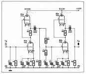
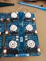
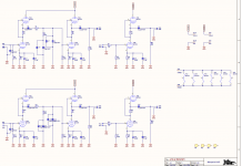
many years before i made a RIAA preamplifier. The circuit was found in a audio magazine, which i don't have anymore, so i built it up and it was working just fine for several years. Theese days i am going to buy a new turntable and want to use this preamplifier. On the photo (the riaa circuit only) you can see the exact same circuit as mine exept the passive riaa filter component values.
In my circuit the riaa filter values are: R6=29.4k , R4=6,1k , C6=82n , C7=22n and everything else, topology and values and tubes are the same.
Can anybody tell me the differences between those two circuits? I can understand that the differences will be in the responce curve but in which way?
Should i try and listen theese two circuits and keep the one that i like more?
thank you
Attachments
You should invest a few hours in learning how to use a simulator. Priceless for anything riaa-related.
I know how use a simulator for the passive Riaa filter. I noticed that the circuit in the photo has about +1.7 dB at 100hz and -0.6 dB at 10khz compared to the other circuit. But I need to know the total response differences including input-output tube impedance etc. That’s what I can’t calculate.
> keep the one that i like more?
> I need to know the total response differences including input-output tube impedance etc. That’s what I can’t calculate.
The playback EQ is a Standard. While you can bend it to suit your ears, it is more sensible to get it *right*, and do your taste-bending and speaker correction in another stage.
I don't think the tubes have much effect here. The grids are infinite-enough. The SRPP output is fairly low impedance and I've used "1k" for a hasty sim.
The "My Circuit" plan looked wrong from the start (220n and 29k is not 50Hz). The bass falls bad. Relative to 1kHz, 50hz is down 4.5dB.
The "Magazine" plan is +0.1/-1.2dB from 20Hz on up (+0.1/-0.6dB 50Hz-up), a fine performance.
Attachments
Last edited:
thank you very much for your answers. If the tubes haven't any effect on the response then i can simulate only the passive filter i find what parts i need for the best performance.
can you suggest, from your experience, a combination for the flattest possible frequency response curve?
As i can see the <magazine> filter performs very well. Should i try to make it better?
can you suggest, from your experience, a combination for the flattest possible frequency response curve?
As i can see the <magazine> filter performs very well. Should i try to make it better?
PRR can you do one more simulation for me? I found that many preamps like this one use the following values:
R6=70k
R4=10.8K
C6=30n
C7=10n
R5=470k and 221K
i need to know if this response will be even better than the previous one.
thank you for helping me
George
R6=70k
R4=10.8K
C6=30n
C7=10n
R5=470k and 221K
i need to know if this response will be even better than the previous one.
thank you for helping me
George
I think puting R5 in front of the filter gives more gain.
Adapting the rest to the mod gives this.
C7 = 15n66 evt put 680p in // with 15n.
Mona
Adapting the rest to the mod gives this.
C7 = 15n66 evt put 680p in // with 15n.
Mona
Attachments
Last edited:
....I found that many preamps like this one use the following values:....
Attachments
The values above are typical however it should be noted that R5 is dependent on the tube used for V1. It will usually be about 92K minus the Ra of the tube (with the shown caps of 30nf and 10nf). So with the tubes shown 70K is a reasonable value. R6 does fit into the calculations and ought to be the 470K value. Often you will see a grid stopper resistor on V2 as well. Values I have seen are in the 4.7K to 22K range. I would suggest a cathode follower be added if the output cables are of any significant length or the input impedance of the following stage is less than about 5K. The linearity of the second SRPP will not be as good below that loading.
as far i can understand from these simulations the response in red color is the <flatter> one. However i will try both versions (in the second version i will use R6= 470KΩ as gofar99 suggested) and measure the total preamp response using the REW software and a 40db-attenuator at the input.
It is a little strange that the blue curve, using same values as the Groovewatt amp does, is not as good as the red one (or at least it seems to be) because of the roll off at lower frequencies. Maybe in this circuit the tubes have an effect on the overall response? or it can be due to the 0.22uF capacitror in the first stage?
It is a little strange that the blue curve, using same values as the Groovewatt amp does, is not as good as the red one (or at least it seems to be) because of the roll off at lower frequencies. Maybe in this circuit the tubes have an effect on the overall response? or it can be due to the 0.22uF capacitror in the first stage?
Last edited:
The tube stages depend on the tube. I see three different types in the drawing in post #1. Using 6DJ8 I get 680 Ohms, using 12AT7 I get 3k. Facing a load 30k-57k and up, the difference is small, but about the size of the error on the best-case values. So you need to define the actual tube and its operating point before refinement can go further.
I don't know what is wrong with the "Magazine" plan.
I don't know what is wrong with the "Magazine" plan.
I am going to use the ecc83s in the first stage and ecc81 in the second stage. The magazine preamplifier and also the other one both uses the same tubes.
If it were me I'd use ECC81 for both stages. I find modern ECC83s kind of flaky. As well, you will likely have the most noise from the first stage tube. Using all ECC81s will allow you to swap them around and put the quietest ones in the first stage. And, vintage ECC81s typically sell for way less vintage ECC83s. You won't be giving up much gain with the '81s.
Steve
Steve
I know how use a simulator for the passive Riaa filter. I noticed that the circuit in the photo has about +1.7 dB at 100hz and -0.6 dB at 10khz compared to the other circuit. But I need to know the total response differences including input-output tube impedance etc. That’s what I can’t calculate.
Not sure what you call a simulator, bit if you really know how to use one all these impedances will become obvious.
In any case the series resistor is usually selected to be much larger than the tube stage output impedance, so that is seldom a factor.
> the series resistor is usually selected to be much larger than the tube stage output impedance, so that is seldom a factor.
Roughly true.
The OP is not satisfied with the apparent +/-2dB errors of his present plan (I agree, though I've used worse). So small differences matter.
We have a suggestion for ECC81/12AT7, which I happened to figure as 3k. I would expect +/-20% deviation around nominal, so +/-600r, total 1200r error. For 1dB error we want the fixed resistor 10X bigger, 12k. For 0.25dB error, 4X of that, 48k. So the 30k-70k values in this thread are in the right ballpark for this tube, pretty much.
Too much higher would require figuring thermal hiss, and beg for stray noise in the high impedance. Let's pencil 60k. But since the tube is 3k, the actual resistor is 57k. At this point you stop and find out what good resistors are in-stock for order.
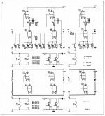
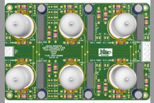
In 2018 i designed a pcb with 3 stages srpp, 2 stages for phono preamplifier and one for line stage, the schematic is from ANZAI, some friends built the preamp.
Attachments
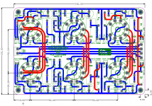
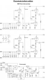
R6-R19 = 62k 😕 , rather 6k2 !In 2018 i designed a pcb with 3 stages srpp, 2 stages for phono preamplifier and one for line stage, the schematic is from ANZAI, some friends built the preamp.
And here the same mistake to put R11 after the filter.Gives a unwanted devider R1-R11. With R11 in front of the filter, before R1, one gets extra free gain. And R11 doesn't need to be that small, 470k will do easely.
The value of R1 changes, the filter sees R1+Rout(SRPP)//R11 but with R11 in front it's now R1 in series with R11//Rout(SRPP)=~Rout.
Mona
- Home
- Amplifiers
- Tubes / Valves
- riaa amplifier