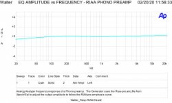
This is the response I intend as linear.
There is a loss 0f 0,6 dB at 20 Hz; ECC83 used.
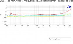
Thr other graph is related to THD vs Freq at three different level of input:
4,1 mV, 8,2 mV and 16 mV; the gain is around 42dB
so 4,1 mV =500mV out
8,2 mV= 1 volt out
16,4 mV = 2 volt out
with Zout of 250 ohm
The shape is good for the three curves also a 20 kHz
In this project it is possible to change the gain tubes modifing the amplification
A new project of tube phono for Audioreview magazine in Italy
Walter
There is a loss 0f 0,6 dB at 20 Hz; ECC83 used.
Thr other graph is related to THD vs Freq at three different level of input:
4,1 mV, 8,2 mV and 16 mV; the gain is around 42dB
so 4,1 mV =500mV out
8,2 mV= 1 volt out
16,4 mV = 2 volt out
with Zout of 250 ohm
The shape is good for the three curves also a 20 kHz
In this project it is possible to change the gain tubes modifing the amplification
A new project of tube phono for Audioreview magazine in Italy
Walter
Attachments
Last edited:
Today I listened to the new turntable with Ortofon 2m silver - preamplifier. I must say that the low and mid are fine but I feel like the higher frequencies need a little boost. But why? The rest of my system is ok. The Riaa preamplifier response is almost flat . Maybe I should try to change the input cap? ( now I have 47p) Or maybe it is because the needle is new?
The input capacitance is given also from the cable , it can be around 120-to 250 pF that you have to add to the real input capacitange ( Cin + C Miller effect of the tube used).
This is a low pass filter.
Also increase the Rin is not the way.
Walter
This is a low pass filter.
Also increase the Rin is not the way.
Walter
See picture.
Attachments
Last edited:
to Koifarm
But this is not the right way to have a better high frequncies!!!!!!
You are moving the resonance frequency!!
Walter
But this is not the right way to have a better high frequncies!!!!!!
You are moving the resonance frequency!!
Walter
But if you pay €400 for a cartridge and you like it but need some more hightones. The impedance change (5 cent) can make you happy. It is fine tuning. It is cheaper then buying new cartridge or new speakers.
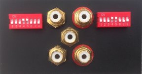
My switchinputboard i also can adjust inputcapacitance.
My switchinputboard i also can adjust inputcapacitance.
Last edited:
No, you are in error!
You must find the way to get the flat response with a right de-emphasis network not from a wrong trick
Your solution give a bad quality of high frequencies with +3dB at 10kHz ( simulated, maybe can be higher in a real world).
Walter
You must find the way to get the flat response with a right de-emphasis network not from a wrong trick
Your solution give a bad quality of high frequencies with +3dB at 10kHz ( simulated, maybe can be higher in a real world).
Walter
I know the riaa network should be flat at 47k input impedance. But fine tuning the sound as I/You like it is easy to change input capacitance and impedance. It is all about the sound you like and not about the perfect specs. Specs are a guideline but tells nothing about if i like the sound.
I know the riaa network should be flat at 47k input impedance. But fine tuning the sound I/You like it is easy to change input capacitance and impedance. It is all about the sound you like and not about the perfect specs. Specs are a guideline but tells nothing about if i like the sound.
hi again,
after your recommendation about the input load
I have found, I believe, the right solution for my problem regarding the high frequencies. I find an user manual from a pro-ject tube phono preamplifier which allows changing the cartridge load capacitor/resistor. In the manual they recommend, for this cartdridge, that i should select 47k and 147p. The cartridge manual recommend a load of 47k and 150-300pF. So i left the resistor as it is (47K) and change only the capacitor from 47p to 150pf as they recommend. The result is that the higs are much more better now.
I think that no matter what load combination i have, when measuring using the 40db pad with the soundcard of my computer the results (frequency response) of the preamp will be the same, that's why i couldn't have understood the problem from this measurement.
But the capacitor i have is a ceramic one. Should i change it to other better type? Or it is ok to be ceramic for this job?
Last edited:
Fine!
Remeber that you have also the capacitance of the cable in addition with the value you set
Leave ceramic and listen the music.
The value is so little.
Walter
Remeber that you have also the capacitance of the cable in addition with the value you set
Leave ceramic and listen the music.
The value is so little.
Walter
Connect the cartridge through the tonearm to the phono preamp input.
Connect a signal generator that is terminated in its characteristic impedance, and from there to a 470k Ohm resistor to the phono preamp input.
Connect your scope 10X probe to the phono preamp input (probe 9 meg in probe, and 1 meg in scope input).
Test the frequency response at the preamp input, from 1 kHz to 30kHz.
This will show you the resonance of the following:
Phono Cartridge Inductance and . . .
The parallel capacitances of the tonearm wire, shielded cable capacitance from tone arm to phono preamp input, capacitor(s) in the phono input to ground (if any), and the miller effect capacitance of the input tube.
The Q of this resonance is primarily controlled by the preamp 47k to ground, and not by the 470k from the generator, and the probe 10 Meg to ground.
You may be surprised at what you see in the measurement!
This electrical resonance is only one of the two resonances that controls the high frequency response of the signal at the phono preamp input.
The other resonance is the mechanical resonance of the diamond tip plus cantilever, as they interact with the vinyl record.
Hmmm . . .
Things are not always as simple as they seem.
Last edited:
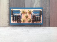
hi,
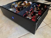
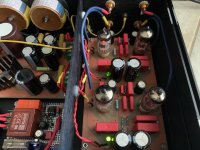
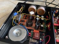
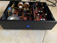
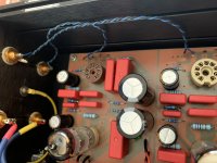
now, when everything works as it should, i am posting a few photos of the preamp. Next, i am going to try a few different tubes that i have.
6a3summer i will definitely try to make a measurement as you said.
thank you
now, when everything works as it should, i am posting a few photos of the preamp. Next, i am going to try a few different tubes that i have.
6a3summer i will definitely try to make a measurement as you said.
thank you
Attachments
I measured the input capacitance of the preamplifier at the input rca and measured 220pf at one input and about 190pf at the other one! The capacitors I have are 150pf. These cables that I have used together with the rca on the chassis adds another 70pf and 40pf due to the length difference. So I changed the shielded coax cables with twisted pair I of the same length and the result is that now I have a total 170pf at both inputs. Now I have learned that twisted pair cables have much lower capacitance.
Attachments
Last edited:
If you are in the range of 250-330 pF total, included the cable from turntable, it is fine.
Look on the MM cartridge specification maybe there is listed the optima capcitance
Walter
Look on the MM cartridge specification maybe there is listed the optima capcitance
Walter
Regarding the mechanical resonance of tonearm-cartridge at low frequencies is the most important value we need; there are some good LP test to do this.
This because it can interact heavy with low range due to the great amplification, around 20 db at 20 Hz of the de-emphasis.
On the high range it became non so important as the right coupling with the input of the phono stage.
This mainly for the MM types, for MC this aspect is less important but there are other istances.
To measure in the right way the total capacitance seen by MM you can use a generator with around 20kHz, some values of capacitors ( 220-270--330-390-470 pF , p.e.) put in series, one by one, with the input of the stage including the connection cable from turntable to phono.
When you read (on the 47 kohm of input of the phono circuit) the 50% of the value of the signal from generator you have exactly the total capacitance.
It is difficult to explain ( in my english) but very easy to do.
This is the way we use on Audioreview lab to find the details of the input of each circuit.
We have a little box with a rotary switch for resistors and capacitors so the reading is more easy.
Walter
Last edited:
The electrical coil and capacitance resonance is one item.
The mechanical tip resonance at high frequencies, is another item.
The two of them together determines the high frequency smoothness or rougness of the complete system.
The low frequency resonance is caused by the cartridge and tone arm mass, and the compliance of the cartridge.
Get this one wrong, and a warped record can cause major problems.
Warp is ~ (about) 3 Hz.
Ideal tonearm/cartridge low frequency resonance is ~ 10 Hz.
If the resonance is higher, it can be activated by some records with low frequency signals.
The problem is not only the resonance freqency that must be around 10Hz, depends also from the shape of it.
And the quality of cartridge and the right tome arm mass ( and construction, of course), helps.
In the high freq. the most important aspect, for MM, are L-C .
Walter
And the quality of cartridge and the right tome arm mass ( and construction, of course), helps.
In the high freq. the most important aspect, for MM, are L-C .
Walter
Last edited:
- Home
- Amplifiers
- Tubes / Valves
- riaa amplifier