Nice, Pano, look forward to the graphs! BTW, are you going over to SY's for a listen & maybe bring some DACs?
Last edited:
You're welcome! No, not going to SYs. He's about 1800 kilometers from here. =)
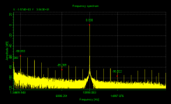
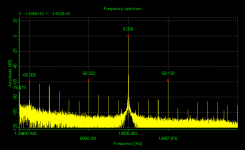
Just as a preview, here are 2 FFTs of my built in RealTek card feeding the analog inputs of an M-Audio USB Fastrack Pro. One is the signal with built in jitter, the other without jitter.
You can see there is a lot of mess down low. But I left the markers in the same place so that you can see the difference. It looks much, much cleaner using the same card for in & out.
Will post more complete stuff later.
Attachments
Not quiet the perfect equipment for analogue waveform analysis as the loopback test would suggest, probably? Would you have the same for loopback graphs? We have a high noise floor & spuriae reaching up to -60dB - hmmm. So this would be the base level. You don't happen to have the cards that SY is intending to use, do you?
Pano, does your software calculate the real noise floor (SNR)? It's not just read from the graph which would give around -100dB (16bit) but somewhat worse than this
Last edited:
Here is the loop back signal with built in jitter in the same card. (M-Audio). Much cleaner.
Don't know how much of the noise above is the Realtek output and how much is the clock mismatch.
I'll look int the rms values. I do not have the same cards as SY.
Don't know how much of the noise above is the Realtek output and how much is the clock mismatch.
I'll look int the rms values. I do not have the same cards as SY.
Attachments
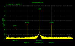
Indeed it isHere is the loop back signal with built in jitter in the same card. (M-Audio). Much cleaner.
Yes it could be from either but the important point is it's showing the full system noise & resolution i.e if this was your measurement system you would have some knowledge & appreciation of what can be revealed by it? Maybe Joseph K, T or indeed SY have something more to say about this.Don't know how much of the noise above is the Realtek output and how much is the clock mismatch.
OK, thanksI'll look int the rms values. I do not have the same cards as SY.
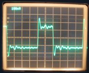

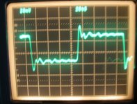
Can you tell us the test set-up, scope, etc. Why 72R? What's your time division? Can you adjust it for a more detailed scope trace? Did you try 10dB + 6dB - one at each end as per the previous scope shots?
20ns per division. Everything else exactly what I've already stated. No, I didn't tandem the attenuators- dropping the signal 16dB is not likely to get my DAC to lock on it.
Why not try it instead of assuming - it can't harm your DAC. I advise you to try this!
Eh, what did you state already - remind me. What scope/speed? etc
Why did you use a 72R termination - you know the SPDIF standard is 175ohm, don't you? You need to give some detail about this set-up for your credibility.
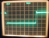
Here's the previous 20ns scope shot with attenuators
Compare & contrast with SY's
Eh, what did you state already - remind me. What scope/speed? etc
Why did you use a 72R termination - you know the SPDIF standard is 175ohm, don't you? You need to give some detail about this set-up for your credibility.
Here's the previous 20ns scope shot with attenuators
An externally hosted image should be here but it was not working when we last tested it.
Compare & contrast with SY's
Last edited:
No analog output difference, no sonic difference, unless you want to invoke Booga-Booga.
this. Why are you posting digital waveforms? 😀 😕
Last edited:
SY could at least have tried the same conditions as have been used for the other scope shots of the SPDIF waveform using 6dB at one end & 10dB at other end of the SPDIF cable. He didn't even try using a 10dB attenuator!
Jitter is flank time differences. Not rise times or overshoot. I would argue that the signal could look like **** as long as the criteria for flank detection is fulfilled in a stable manner between every pulse. But please correct me!
This is of course only interesting if one extracts the clock form the SPDIF link. If a system don't, the only bad that can happen from a poor link is actual data loss as such a regime would be absolutely indifferent to SPDIF jitter.
(Then someone argued that it has a DC component i.e. trailing ones but SPDIF is coded NRZ and bi-phase mark so it hasn't)
/
So what are the criteria for stable detection of "flank detection" on every pulse?Jitter is flank time differences. Not rise times or overshoot. I would argue that the signal could look like **** as long as the criteria for flank detection is fulfilled in a stable manner between every pulse. But please correct me!
/
I hope you mean 75 ohm. It's the same as composite video. 72 ohm won't hurt it.- you know the SPDIF standard is 175ohm, don't you?
Looks the same, just lower. The attenuators work.Hiface spdif signal at receiving end, setup as before, two attenuators.
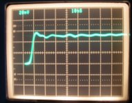
same setup (50ns per division for one trace,
The time division looks different. Is it?
- Status
- Not open for further replies.
- Home
- Source & Line
- Digital Source
- RF Attenuators = Jitter Reducers