The TO220s are the drivers for the output transistors. I've noticed a lot of variation in bias current with the drivers mounted on their own heat sinks with the new output devices. Everything is more stable with them mounted on a larger hunk of aluminum.
The output devices are MJL4302/4281. They're rated for 350V so if anyone is psychotic enough to try it 100+ rails should theoretically be possible. I have a 64VAC transformer kicking around so I could do some testing at +/- 90V rails but I don't need that much power for anything so I wouldn't run it like that.
I'm planning to test this in a 5U 16" deep convection cooled chassis. It'll be a pretty heavy to move around but it should cool fine with +/- 70V rails.
Yes i know that's the drivers but how many drivers?
Yes i know that's the drivers but how many drivers?
As far as I can see there are only two TO220 transistors on the output board, so it should be two drivers.
There are two pairs of drivers and two pairs of clamping transistors. I'll explain the driver heat thing when I get to a PC. Phone isn't cooperating.
I see only two TO220 on the right of the board.
Where are the other two?
Those on the left are not TO220s.
Where are the other two?
Those on the left are not TO220s.

In earlier designs I had each driver mounted on it's own heat sink with the non-switching transistor mounted on the opposite side. With the old Sanken drivers and outputs and drivers this configuration worked okay. When I began experimenting with the ON Semi drivers and outputs I found that bias current was pretty much zero when I first powered it up and remained there until the amp was put to work. This was leading to a cold sounding amp that needed to warm up.
Driver heat sink temperature had a very large effect on the bias current. The driver heat sink really changes temperature with amplifier load which I assumed was due to the non-switching transistor, the driver's are in class A so load shouldn't make a difference. In some early designs I had mounted the driver directly on the main heat sink and found the bias current was more stable so I decided to test this out on the new On Semi drivers. A larger chunk of aluminum stuck to the driver heat sink seemed to stabilize the bias current.
In this design the drivers are on the main heat sink so their temperature won't vary as quickly plus I have an extra temperature sensing transistor for the bias circuit mounted on the main heat sink raising the temperature co-efficient of the bias circuit so hopefully bias won't vary as much on warm up. I hate having an amp that needs to warm up to sound good!
Apparently a pair of drivers seems to serve a pair of output transistors.
Doesn't that demand matching all the drivers, with the extra cost that supposes.
To me that's the problem with some Goldmund versions, as that is difficult (and expensive) to do in DIY.
Doesn't that demand matching all the drivers, with the extra cost that supposes.
To me that's the problem with some Goldmund versions, as that is difficult (and expensive) to do in DIY.
Each driver pair runs three output pairs. The only matching I do is use transistors from the same manufacturing batches. On Semi's parts match very well out of the box.
Apparently a pair of drivers seems to serve a pair of output transistors.
Doesn't that demand matching all the drivers, with the extra cost that supposes.
To me that's the problem with some Goldmund versions, as that is difficult (and expensive) to do in DIY.
Yes, as Jeff just mentioned, each pair of drivers serves 3 output pairs.
All drivers are loaded with the constant current sources. So each pair of drivers employs 4 transistors, not 2 of them.
No particular matching required - if hFE difference is less than 2x it's no problem.
Cheers,
Valery
Last edited:
What exactly do the clamping transistors? Limiting?
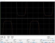
Limiting the minimum bias. This is a part of the non-switching mechanism. There is a second bias spreader, setting the minimum bias used when the positive or negative half of the OPS is not used, preventing the output transistors from closing. As soon as the bias voltage reaches that minimum voltage, it gets clamped there.
The attached image shows a close-up of the crossover region of the output stage (voltage drop over the emitter resistors, proportional to the collector current). You can see the voltage does not drop to zero, being clamped at a certain value - output transistors never close.
Attachments
Where can I see the schematic of that amp?
This is the OPS module.
Zobel / Thiele networks, protection circuitry, SS relays, binding posts are placed on the separate board. IPS modules are interchangeable - a good choice of front-ends for different applications and/or tastes is available.
Cheers,
Valery
Attachments
Which transistors are the clampers?
How do you adjust both bias spreaders? With a scope?
Here are the instructions including the setup procedure:
http://www.diyaudio.com/forums/solid-state/277087-revisiting-ideas-1970s-ips-ops-35.html#post4554894
This three has got an index in the 1-st post - NS OPS is number 5. You can find a lot of useful stuff there 😉
Nice work, will you also offer a "normal" version of the NS-Outputstage with only 3 output pairs?
Nice work, will you also offer a "normal" version of the NS-Outputstage with only 3 output pairs?
We've had the normal three pair version available for a couple of years. It's on our website.
We've had the normal three pair version available for a couple of years. It's on our website.
Strongly recommended, tested many-many times without any issue.
Very good sounding, strong, dynamic, an excellent choice!
I'm sure new version will be a step farther, better, more powerful, a real Monster. It will be able to undertake any task assigned to it, earthquake or melody.
Last edited:
This is this the version with the MT-200 Sanken Output, isn't it?We've had the normal three pair version available for a couple of years. It's on our website.
- Home
- Amplifiers
- Solid State
- Revisiting some "old" ideas from 1970's - IPS, OPS