Sauberkeit
Hi Jeff,looking at the Sauberkeit schematic i can't see the R C( C15 R24 ).
I see this on pcb.
Is it an existing circuit or not?
Hi Jeff,looking at the Sauberkeit schematic i can't see the R C( C15 R24 ).
I see this on pcb.
Is it an existing circuit or not?
Last edited:
This time i'm getting in troubles.😱
Testing this new IPS(as stand alone) i see 40v d.c or sometimes 16v d.c output.
Q4 is very-very hot.
Feedback resistors R22 R23 Very hot.
Pulling out the op amplifier,output is 1v d.c and nothing is hot.
Is the op amplifier unstable?
Testing this new IPS(as stand alone) i see 40v d.c or sometimes 16v d.c output.
Q4 is very-very hot.
Feedback resistors R22 R23 Very hot.
Pulling out the op amplifier,output is 1v d.c and nothing is hot.
Is the op amplifier unstable?
Attachments


Last edited:
This time i'm getting in troubles.😱
Testing this new IPS(as stand alone) i see 40v d.c or sometimes 16v d.c output.
Q4 is very-very hot.
Feedback resistors R22 R23 Very hot.
Pulling out the op amplifier,output is 1v d.c and nothing is hot.
Is the op amplifier unstable?
Hi Thimios,
Let me refresh my memory and think a bit 🙂
I will come back soon.
Cheers,
Valery
Ok Valery, l have spent my day testing for incorrect or fault components but nothing.Hi Thimios,
Let me refresh my memory and think a bit 🙂
I will come back soon.
Cheers,
Valery

I don't remember if I ever mine going. I was having issues with this input too.
Aha now i'm sure the problem is on the op amplifier.
I have a full test with a removed i.c.
The pin 6 used as AF input.
I will post latter.
Last edited:
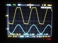
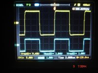
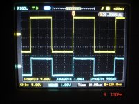
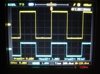
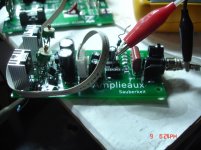
Troubleshooting the Sauberkeit
The i.c was removed and pin 6 used as AF input.
Yellow waveform is the output signal
Blue is the input signal.
Tomorrow i will post voltage measurements.
The i.c was removed and pin 6 used as AF input.
Yellow waveform is the output signal
Blue is the input signal.
Tomorrow i will post voltage measurements.
Attachments
Last edited:
The DC protect part of the speaker protection system should keep the speakers protected from the rail dc offset before the tube warms up.
That's what I've been assuming before my posting #2708. The 21st century board shuts down the amplifier completely instead, so I've been told.
Best regards!
Best regards!
I did that with my car stereo amplifier as the space constraints demanded something small.
the speaker protect cut the power to the SMPS chip via the remote turn on control. The energy held in the storage caps is all that could reach speakers.
THe 21st Century board shuts off the amp after the reservoir caps so that energy is not shorted or sent to speakers.
the speaker protect cut the power to the SMPS chip via the remote turn on control. The energy held in the storage caps is all that could reach speakers.
THe 21st Century board shuts off the amp after the reservoir caps so that energy is not shorted or sent to speakers.
Last edited:
The DC protect part of the speaker protection system should keep the speakers protected from the rail dc offset before the tube warms up.
Well, the algorithm at startup is as follows:
The speaker relay is disconnected, everything is off.
- Power On signal comes to the control board;
- Tube filament PSU goes on - delay 25 seconds;
- Inrush relay goes on - delay 5 seconds;
- Main Power relay goes on, after 0.5 seconds Inrush relay goes off, delay 10 seconds (power amp balances itself, offset disappears).
Now the control board checks if there's no offset and no overcurrent in the OPS.
If everything is fine, it connects the speakers and monitors all the sensors continuously (DC offset, Overcurrent, Overtemperature, AC failure).
If there is some problem - it shuts down the amp and indicates what the problem is. There's no attampt to connect the speakers in this case.
All delays are adjustable with 1 millisecond granularity.
Last edited:
Ok Valery, l have spent my day testing for incorrect or fault components but nothing.
Hi Thimios! My stupid mistake again

Opamp's inputs are swapped.
You need to swap them back one way or the other (pins 2 and 3) before you plug the opamp back in place.
The impedance of the feedback network is rather low, so the VAS is slightly overloaded by it, however, it will balance itself and work - just distortion level will be higher. Never mind, as soon as you connect the OPS later on, impedance conditions will become normal for Sauberkeit.
Sorry for all the trouble. I hope, now it's going to go smoothly.
Hi Valery,don't worry, i will cut two traces for easy correction.😉Hi Thimios! My stupid mistake again
Opamp's inputs are swapped.
You need to swap them back one way or the other (pins 2 and 3) before you plug the opamp back in place.
The impedance of the feedback network is rather low, so the VAS is slightly overloaded by it, however, it will balance itself and work - just distortion level will be higher. Never mind, as soon as you connect the OPS later on, impedance conditions will become normal for Sauberkeit.
Sorry for all the trouble. I hope, now it's going to go smoothly.
delaying turn on of main system by 25 seconds will make the offset minimal as the tube has warmed up sufficiently to work. smart move
delaying turn on of main system by 25 seconds will make the offset minimal as the tube has warmed up sufficiently to work. smart move
Yes, that's the point 🙂
Some thump is still there on the OPS power on, but the offset zeroes out quickly as the tube is already working, way before the speakers are connected.
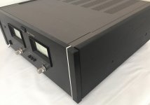
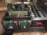
Tribute 3000
I have the Tribute 3000 driver and OPS boards installed in The Sansui Ba-2000 chassis It is running nicely. I haven't connected it to my good speakers yet as my biggest problem was connecting the new boards to the old driver board supply and protection system. The basic soft start works but I have no speaker protection at this time. I think its a candidate for the " 21st century control board".
I'm very happy with the results. Thank you Valery for the design and assistance.
Jeff what is the size of the new control board. I have a spare amp control 4.3 12/13/15 but the new board may be easier to fit in.
Attachments

Last edited:
- Home
- Amplifiers
- Solid State
- Revisiting some "old" ideas from 1970's - IPS, OPS