I hope today will be "Tested"BeautifulReady to power-on? 😎
Would the Shunt Power Supply is an upgrade option for the +/-15V input power supply?
Last edited:
I hope today will be "Tested"
Would the Shunt Power Supply is an upgrade option for the +/-15V input power supply?
We should have a new input stage power supply for you to test in the next few weeks. I have my doubts that it would be required as PSSR is good but we're going to try anyways.
Last edited:
The finest is the enemy to the good!We should have a new input stage power supply for you to test in the next few weeks. I have my doubts that it would be required as PSSR is good but we're going to try anyways.
Jeff,what about of the DIY Full Featured Preamp
?
I hope you are in a good way.🙂
I'm still working on the preamp. I'm about to order boards to test a USB audio interface using a XMOS audio processor and also a VHex headphone amp for evaluation. If I like what I see I'll do versions of both to fit into the preamp chassis.
I'm getting in troubles,The lamp in series with transformer primary side and two 18R 10W instead of the fuses saved the OPS.....
Attachments
Last edited:
Will R8 adjust the DC offset closer to 0? it looks like everything is operating nicely other than the DC offset. 5.5mA VAS current is perfect.
Will R8 adjust the DC offset closer to 0? it looks like everything is operating nicely other than the DC offset. 5.5mA VAS current is perfect.
No,offset can't be trimmed to zero.Yes - looks good to me as well if you can zero-out the offset.
The biger problem is that this IPS when connected to OPS i measure 20v on the protective 18R/10W resistors(instead of fuses) even if the bias trimmer is at the minimum bias position.😕
Input pair is 2N5088.
As the VAS current is correct is it possible an oscillation problem?
But the offset problem?
Last edited:
it would be better to work with the input in standalone mode until it's debugged, then figure out the output board issue. Doe DC offset move at all when adjusting R8? if so which way is the pot stopping at? Max or minimum? R9 needs to be changed sometimes. Valery says this is due to different forward voltage in different LEDs.
For zeroing out the offset - adjust the value of R9 - if your trimmer, being at the lowest offset position, is showing zero value - decrease R9. If the trimmer shows its maximum value - increase R9.
Oscillation - possible. I always have an oscilloscope connected to the output of the amp on a test bench - you can see what's going on right away 😉
Oscillation - possible. I always have an oscilloscope connected to the output of the amp on a test bench - you can see what's going on right away 😉
The output board haven't any issue as work well using all other IPS.it would be better to work with the input in standalone mode until it's debugged, then figure out the output board issue. Doe DC offset move at all when adjusting R8? if so which way is the pot stopping at? Max or minimum? R9 needs to be changed sometimes. Valery says this is due to different forward voltage in different LEDs.
The offset trimmer isn't possible to zero the offset and i don't believe that do the job well.
Ok,i will reinstall the IPS using lamp,protective resistors and oscilloscope looking for a possible oscillations.
The offset problem is another story.
Last edited:
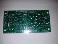
Good!I have finally got TubSuMo squeezed onto an input board for the NS-OPS series amps.😀
Another IPS to the family!😎
Attachments

Last edited:
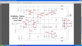
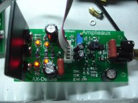
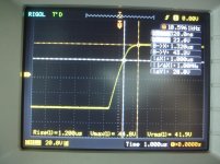
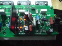
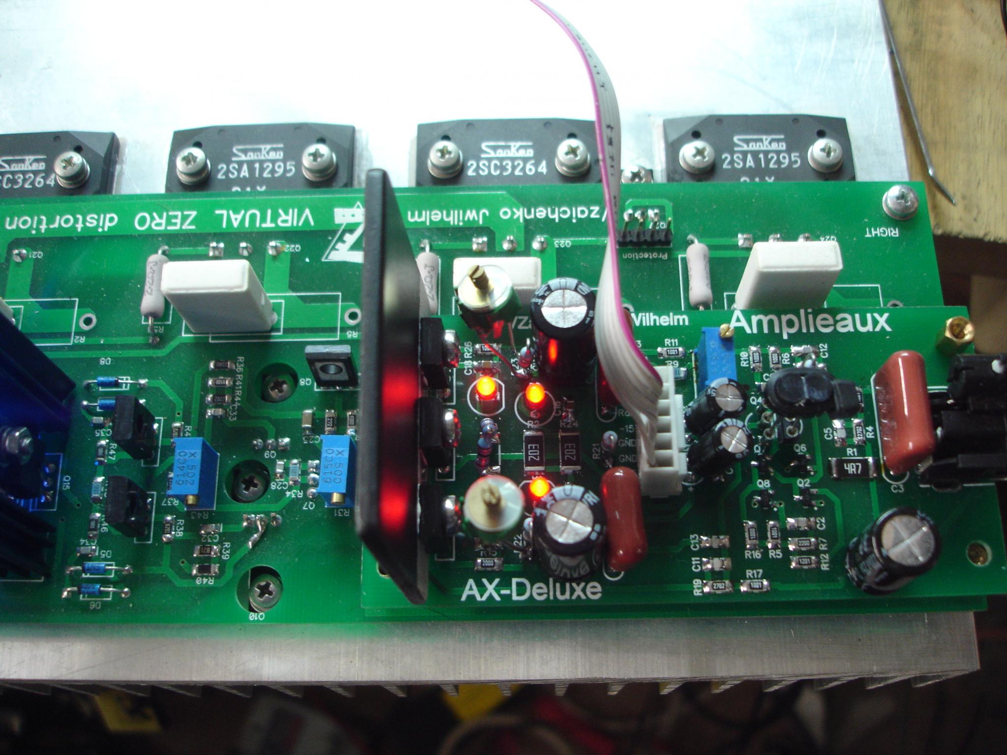
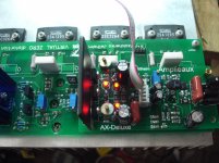
Testing the A-X Deluxe as stand alone IPS.
The offset problem solved using 390R//1K.
As i can't see other problem here i'm afraid that this IPS oscillate when connected to OPS.
Attachments
-
 DSC09458.jpg250.6 KB · Views: 682
 -
 DSC09444.jpg278.3 KB · Views: 124
 -
 DSC09446.jpg280.9 KB · Views: 120
 -
 DSC09448.jpg304.4 KB · Views: 119
 -
 DSC09455.jpg308 KB · Views: 115
 -
 DSC09454.jpg272.2 KB · Views: 106
 -
 DSC09453.jpg290.7 KB · Views: 112
 -
 DSC09452.jpg292 KB · Views: 113
 -
 DSC09449.jpg294.5 KB · Views: 114
Last edited:
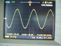
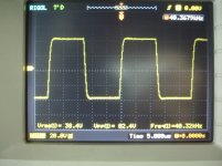
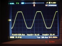
A-X Deluxe

Arrested!
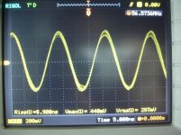
Amplifier oscillate at 56.5Mhz,see picture.
This measured without any load when input is open.
Arrested!
Amplifier oscillate at 56.5Mhz,see picture.
This measured without any load when input is open.
Attachments
Last edited:
OK - 450mV - not too "evil" )
No additional capacitors, mentioned in my previous post, right?
No additional capacitors, mentioned in my previous post, right?
Right,47pf// to R22 R23 not added yet.BUT the lamp in series with transformer primary side and the protective resistors(instead of fuses) are in circuit.OK - 450mV - not too "evil" )
No additional capacitors, mentioned in my previous post, right?
I see 7v d.c on 18R/10W resistors.
Last edited:
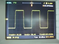
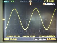
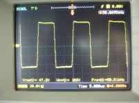
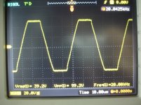
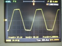
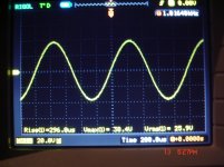
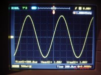
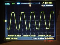
AX-Deluxe+NS
33pf trimmer// R22,R23.
This way amplifier is stable but i see a little warm zobel resistor even with sinusoidal at clipping levels.
Test conditions:+/-50V.
75.000uf/rail
22mA/Pair idle current.
R dummy=6R
980mV input, 26.6V RMS/6R=118W RMS out,or 176W/4R.Just before clipping.
-3db,2.5Hz-300Khz.
33pf trimmer// R22,R23.
This way amplifier is stable but i see a little warm zobel resistor even with sinusoidal at clipping levels.
Test conditions:+/-50V.
75.000uf/rail
22mA/Pair idle current.
R dummy=6R
980mV input, 26.6V RMS/6R=118W RMS out,or 176W/4R.Just before clipping.
-3db,2.5Hz-300Khz.
Attachments

Last edited:
- Home
- Amplifiers
- Solid State
- Revisiting some "old" ideas from 1970's - IPS, OPS