That's the right board. Left and right are marked on a corner on each board. I haven't tried to run my right board yet, but both are from the same schematic and both verify the same in Diptrace, so they should both have the same error, unless the board house messed up.
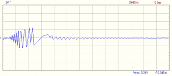
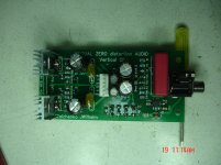
This output board has been pretty interesting so far! I've been trying to nail down a proper set of values for the bias circuit, but it's not going well. I installed 1k2 for R34 and a 200R trim pot and wasn't able to acheive any bias current. I replaced R34 with 1k1 and wasn't able to lower bias enough. i reinstalled 1k2 and wasn't able to turn bias off. I think I'm seeing high frequency oscillation bursts on the output.
Attachments
This output board has been pretty interesting so far! I've been trying to nail down a proper set of values for the bias circuit, but it's not going well. I installed 1k2 for R34 and a 200R trim pot and wasn't able to acheive any bias current. I replaced R34 with 1k1 and wasn't able to lower bias enough. i reinstalled 1k2 and wasn't able to turn bias off. I think I'm seeing high frequency oscillation bursts on the output.
Jeff this looks like oscillation bursts.
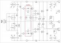
Let's go bold and implement DynaDrive schematic, cutting a couple of traces - its phase characteristics are dramatically better, so the issue is going to go away. Also note the values between the pre-drivers and drivers emitters.
If it goes well, we will publish the changes - Terry will be able to implement them as well.
Does it sound good?
At least the base stoppers for the drivers are required - sorry I did not notice the issue at the initial design. 47R in parallel with 680pF between the pre-drivers emitters and drivers bases will do the trick.
At least the base stoppers for the drivers are required - sorry I did not notice the issue at the initial design. 47R in parallel with 680pF between the pre-drivers emitters and drivers bases will do the trick.
This stuff keeps it interesting! If they all started up and worked like they should it would be a pretty boring hobby!
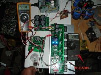
I'm populating 5 different amps right now. Finishing them as the parts come in. I'm not used to having to order parts to build, usually just to restock. The SMD thing is throwing a fly in the ointment.
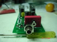
This OPS is a strange one. I tried following the circuit but with most of the parts surface mount I had to keep flipping the board trying to follow the vias. A new learning curve for sure. I will await your findings.
This OPS is a strange one. I tried following the circuit but with most of the parts surface mount I had to keep flipping the board trying to follow the vias. A new learning curve for sure. I will await your findings.
Any ideas what I should be doing to the bias spreader to increase the voltage enough to operate?
DynaDrive
Hi Terry and All,
Jeff has tested the updated circuit.
I gave it the name DynaDrive. It's based on NS-OPS, but is significantly simplified, missing all the clamping mechanism. However, the diodes in series with the drivers' bases compensate a lot of the OPS non-linearity. In addition to that, phase response is significantly improved.
Jeff's tests went well with Vertical-VFA and X4 front-ends. There are still some strange "bursts" approximately once in a second. We are still thinking about their nature. There is a possibility they are related to this particular layout of the OPS.
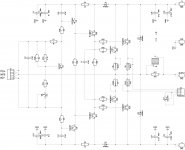
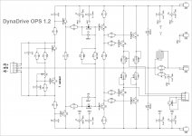
I have attached the original mini-OPS and the one with DynaDrive circuit.
What I would recommend - on your test board, leave the spreader as is (you will only have to decrease the value of the resistor in series with the bias trimmer in order to increase the bias).
Just add the DynaDrive circuit (you will have to cut 2 traces at the drivers' bases). If you don't have 10K NTC in hand - no problem, just use the normal resistor.
Then try it with Vertical-VFA and/or X4. These are going to play nicely.
Meanwhile, we are trying to solve the puzzle with CFA IPS.
Cheers,
Valery
Hi Terry and All,
Jeff has tested the updated circuit.
I gave it the name DynaDrive. It's based on NS-OPS, but is significantly simplified, missing all the clamping mechanism. However, the diodes in series with the drivers' bases compensate a lot of the OPS non-linearity. In addition to that, phase response is significantly improved.
Jeff's tests went well with Vertical-VFA and X4 front-ends. There are still some strange "bursts" approximately once in a second. We are still thinking about their nature. There is a possibility they are related to this particular layout of the OPS.
I have attached the original mini-OPS and the one with DynaDrive circuit.
What I would recommend - on your test board, leave the spreader as is (you will only have to decrease the value of the resistor in series with the bias trimmer in order to increase the bias).
Just add the DynaDrive circuit (you will have to cut 2 traces at the drivers' bases). If you don't have 10K NTC in hand - no problem, just use the normal resistor.
Then try it with Vertical-VFA and/or X4. These are going to play nicely.
Meanwhile, we are trying to solve the puzzle with CFA IPS.
Cheers,
Valery
Attachments
I'll do up some instructions for modifying the boards later this evening. It's pretty confusing trying to follow the schematics and figuring out what traces to cut. The DynaDrive circuit can be butchered onto the bottom of the board fairly easily. Updates to the bias spreader are pretty ugly, not worth the effort.
Why the clamping is missing?Hi Terry and All,
Jeff has tested the updated circuit.
I gave it the name DynaDrive. It's based on NS-OPS, but is significantly simplified, missing all the clamping mechanism. However, the diodes in series with the drivers' bases compensate a lot of the OPS non-linearity. In addition to that, phase response is significantly improved.
Jeff's tests went well with Vertical-VFA and X4 front-ends. There are still some strange "bursts" approximately once in a second. We are still thinking about their nature. There is a possibility they are related to this particular layout of the OPS.
I have attached the original mini-OPS and the one with DynaDrive circuit.
What I would recommend - on your test board, leave the spreader as is (you will only have to decrease the value of the resistor in series with the bias trimmer in order to increase the bias).
Just add the DynaDrive circuit (you will have to cut 2 traces at the drivers' bases). If you don't have 10K NTC in hand - no problem, just use the normal resistor.
Then try it with Vertical-VFA and/or X4. These are going to play nicely.
Meanwhile, we are trying to solve the puzzle with CFA IPS.
Cheers,
Valery
Why the clamping is missing?
For simplicity 🙂
NS Modular boards you've got are, let say, the "full option" ones. Top notch.
We still love them, but some people may be "scared" by the level of complexity.
DynaDrive OPS is almost as simple as a normal EF3.
But better performance.
Jeff, did you build the right channel to see if it works properly? I haven't checked to see if maybe the vbe was ok on that one. I'm letting mine sit until you get a little farther along. I'm also going to wait for the newer layout for the X4. I still have a problem with one of the boards and don't see the sense of listening to only one channel.
I've got the right channel built, but haven't installed it on a heat sink yet. I'm not sure how soon I can get it mounted and tested. I have a feeling yours is oscillating.
Ok got!For simplicity 🙂
NS Modular boards you've got are, let say, the "full option" ones. Top notch.
We still love them, but some people may be "scared" by the level of complexity.
DynaDrive OPS is almost as simple as a normal EF3.
But better performance.
I will try to test the CFA IPS soon .I haven't any 100pf SMD (compensation caps not 5k6 SMD (feed back resistors).
I will try some thru hole 5k6 and 82pf smd.
- Home
- Amplifiers
- Solid State
- Revisiting some "old" ideas from 1970's - IPS, OPS