Here is what i have.
This is the VFA IPS.
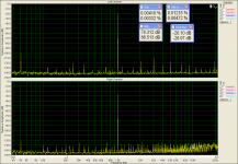
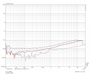
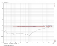
Tested at clipping levels direct on dummy load.
First is the 20Hz test
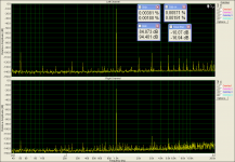
Second the 20KHz
Ummm... did you measure with integrating RC? The curves look like the peak values are measured at some moments in time. How often the values are taken? Normally, DC offset does not change that fast.
I just ran some quick sine sweeps through the VHex+. No sign of DC offset even with hard clipping right up to 30kHZ. The highest offset voltage I saw was 10mV. It usually wanders around at less than 3mV. Nice balanced little amp!
OK, that's what I expected. Let's test X4 front-end with no servo, but with 220uF electrolytic in series with 1K resistor, connected to the feedback junction point. I expect it to be somewhat similar.
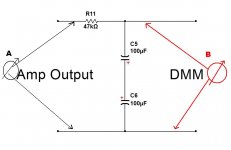
I have attach the low pass filter on the dummy and measure pre and after using an A and B multimeters.
after the filter (B multimeter measure no d.c)
What i post earlier is what the A multimeter show.This set for save interval 0.5sec
Yes Valery, maybe we can do this without servo but this way never we know why this servo not serve well.
after the filter (B multimeter measure no d.c)
What i post earlier is what the A multimeter show.This set for save interval 0.5sec
Yes Valery, maybe we can do this without servo but this way never we know why this servo not serve well.
Attachments
Last edited:
Right. Multimeter A shows the peak values of AC curve, taken every 0.5S then. It makes sense to place both multimeters behind the filter. DC offset never changes that fast - it's a slow process.
I can't understand,meter A say v.d.c,and this occurs only when clipp levels or near this 😕Right. Multimeter A shows the peak values of AC curve, taken every 0.5S then. It makes sense to place both multimeters behind the filter. DC offset never changes that fast - it's a slow process.
Why meter B don't measure any d.c when meter A show d.c.v even if used simple as voltmeter(not record mode)?
Last edited:
I can't understand,meter A say v.d.c,and this occurs only when clipp levels or near this 😕
Why meter B don't measure any d.c when meter A show d.c.v even if used simple as voltmeter(not record mode)?
Meter A shows you instantaneous values at different places of AC curve. In order to see, if there is a DC component in your AC signal, you need to integrate. Meter B shows correct DC values, as it is placed behind the integrating circuit. Meter A shows instantaneous values every 0.5 sec, wherever on AC curve it appears at that moment.
Attachments

I continue thinking about the possible scenario...
Was it playing some music? Or was it just starting playing?
I mean, the amp's bandwidth at the lower end goes below 1Hz. If some step comes to the input and stays for some time - it will immediarely appear at the output and start falling back to zero, but tather slowly.
Also, during the sweep, due to some internal imbalance of the circuit, some DC component may appear for some time, until the servo zeroes it out. With 4.7uF, we have rather slow servo. 1uF makes it fast enough to react on time for all the possible disturbances.
As a last resort - I always have a protection system on my test bench. DC coupled amplifier is always dangerous 😉
I've got protection tripped on my Audiolab 8000x7 tripped the other day. Quick troubleshooting showed one of the electrolitic capacitors has shorted after around 3 years of perfect operation.
If protection would not be there - most likely one of the speakers would be in trouble.
It's like skydiving 🙂 You never know when you will need the reserve. But when you need it - it must be available. I used mine 4 times throughout my career 😉
Enough with the servo circuit.
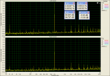
Modular distortion measurements.
Where left channel is the amplifier,where right channel is the sound card loop.(out to in)
Please keep in mind that this is what my sound card can measure.
Modular distortion measurements.
Where left channel is the amplifier,where right channel is the sound card loop.(out to in)
Please keep in mind that this is what my sound card can measure.
Attachments
Last edited:
Not bad at all. Interesting - the card's harmonics increase at higher amplitudes, but the amp's ones stay virtually the same, even slightly decrease )) Possibly - slight under-biasing. Plus, the bias clamping spreader may be not tuned-up for the optimum.
If my memory serve well your recommendation is 35mA idle current,8mV on R22 emmiter resistor,without load,then the amplifier driven with 1Khz sinewave for a 10v RMS out on the load and trim the bias clamping for 5mA increasing(9mv on R22),right?Not bad at all. Interesting - the card's harmonics increase at higher amplitudes, but the amp's ones stay virtually the same, even slightly decrease )) Possibly - slight under-biasing. Plus, the bias clamping spreader may be not tuned-up for the optimum.
Last edited:
Clamping tuning seems to change with output board layout and input selection. They all seem to change the reaction speed of the trim pot. It's likely best to tune it with a distortion analyzer attached.
If my memory serve well your recomentation is 35mA idle current,8mV on R22 emiter resistor,without load,then the amplifier driven with 1Khz sinewave for a 10v RMS out on the load and trim the bias clamping for 5mV increasing(13mv on R22),right?
If I recall correctly bias should be around 50mA, 20mV across a pair of emitter resistors.
Clamping tuning seems to change with output board layout and input selection. They all seem to change the reaction speed of the trim pot. It's likely best to tune it with a distortion analyzer attached.
Yes, that's the best way.
Clamping tuning seems to change with output board layout and input selection. They all seem to change the reaction speed of the trim pot. It's likely best to tune it with a distortion analyzer attached.
Focusing to what thing?Yes, that's the best way.
To the lowest THD?
If I recall correctly bias should be around 50mA, 20mV across a pair of emitter resistors.
I ran mine at 65mA.
Optimum is somewhere in the range of 65-75mA.
Here is my initial setup procedure description:
http://www.diyaudio.com/forums/soli...e-old-ideas-1970s-ips-ops-35.html#post4554894
I have managed to tune-up my board for 0.0005% @1KHz (50W @ 8 ohm), increasing to 0.0007% at 20KHz 😱
I can't measure down to this low THD ,i haven't the equipment🙁I ran mine at 65mA.
Optimum is somewhere in the range of 65-75mA.
Here is my initial setup procedure description:
http://www.diyaudio.com/forums/soli...e-old-ideas-1970s-ips-ops-35.html#post4554894
I have managed to tune-up my board for 0.0005% @1KHz (50W @ 8 ohm), increasing to 0.0007% at 20KHz 😱
Focusing to what thing?
To the lowest THD?
Yes.
First, set the bias with no signal to 65-70mA per pair.
Then, give it stable 1KHz and rotate the clamping spreader's trimmer from some middle position (no clamping) to position, when it just starts clamping.
Optimum (lowest THD) is just in the beginning of clamping.
But do it slowly and carefully, monitoring the bias all the time.
If you quickly set the clamping to some high position, you may have a big bang (current rail to rail shoot-through).
I can't measure down to this low THD ,i haven't the equipment🙁
Just make some minimum. If you can't measure it - it's already good enough 🙂
Yes.
First, set the bias with no signal to 65-70mA per pair.
Then, give it stable 1KHz and rotate the clamping spreader's trimmer from some middle position (no clamping) to position, when it just starts clamping.
Optimum (lowest THD) is just in the beginning of clamping.
But do it slowly and carefully, monitoring the bias all the time.
If you quickly set the clamping to some high position, you may have a big bang (current rail to rail shoot-through).
Hmm... I have been using 80mA bias on my VHeX+ would it have lower THD following this process? Use 10R safety resistors during adjustment can save from Big Bang.
- Home
- Amplifiers
- Solid State
- Revisiting some "old" ideas from 1970's - IPS, OPS