Well, your protection circuit tripp at bout 1.2 v right?
Under test conditions using original vz-x4 dont tripp even when soft clipp ,right?
If this occurs then my burned woofer haven't to do with d.c out....but i remember seeing the cone in a <<long travel>> before death
Under test conditions using original vz-x4 dont tripp even when soft clipp ,right?
If this occurs then my burned woofer haven't to do with d.c out....but i remember seeing the cone in a <<long travel>> before death
Last edited:
Well your protection circuit tripp at bout 1.2 v right?
under test conditions using original vz-x4 dont tripp even when soft clipp ,right?
If this occurs then my burned woffer haven't to do with d.c out....
Yes, looks like... maybe it was already damaged to some extent and our three-pairs-of-Sankens welding machine gave it the last kick

The first test of the SMT design DC detection was actually done in the VHex+ prototype. I literally copy and pasted this section of the DC detection portion of the schematic and ran with it in the standalone protection board. The only false triggering I ever encountered on it was if I physically touched the detection section of the board. I think static charges may trigger it.
As a side note, I'm off to visit Anatech tomorrow and plan to take the VHex+ along for some in depth measurements.
As a side note, I'm off to visit Anatech tomorrow and plan to take the VHex+ along for some in depth measurements.
Last edited:
Well, your protection circuit tripp at bout 1.2 v right?
Under test conditions using original vz-x4 dont tripp even when soft clipp ,right?
If this occurs then my burned woofer haven't to do with d.c out....but i remember seeing the cone in a <<long travel>> before death
One of my boards wouldn't trip it, but the other one does quite regularly, even on a soft clip. It goes negative too, so this sounds like what you may have had happen.
I wish soYes, looks like... maybe it was already damaged to some extent and our three-pairs-of-Sankens welding machine gave it the last kick
May be a <<tuned>>bass mp3 pushed this harder
Is the original that goes negative?One of my boards wouldn't trip it, but the other one does quite regularly, even on a soft clip. It goes negative too, so this sounds like what you may have had happen.
The one I've been modifying since last night goes negative. I haven't actually measured the other one yet. I didn't realize which one it was when I had it plugged into the output board. Just out of curiosity i'm going to measure it now.
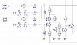
i wonder if this will be a working circuit or a separate power supply for transistor is necessary
Attachments
Last edited:
I mean, testing VHex with the sweep and 20KHz close to clipping and clipping conditions, to see if its behaviour is different somehow, as it's got no servo.
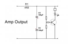
i wonder if this will be a working circuit
As a clipping indicator?
It will potentially work only with positive DC, plus DC has to be rather high to light the LED 😉
This is the DC detecting circuit we used in the early version of 2-st century protection. Works for any polarity, very precise and reliable.
Great advantage - you can track as many channels as you need, just adding RC and 2 diodes to each channel and connecting them to the bases of this single sensor.
Convenient for multi-channel amplifiers (5, 7, etc.).
Great advantage - you can track as many channels as you need, just adding RC and 2 diodes to each channel and connecting them to the bases of this single sensor.
Convenient for multi-channel amplifiers (5, 7, etc.).
Attachments
I mean, testing VHex with the sweep and 20KHz close to clipping and clipping conditions, to see if its behaviour is different somehow, as it's got no servo.
I plan to do this sort of testing on the VHex tomorrow. Right now it's still hooked up in my living room at home. I use it every day.
I plan to do this sort of testing on the VHex tomorrow. Right now it's still hooked up in my living room at home. I use it every day.
Ah! I see.
Meanwhile, I came up with fantastic method of balancing the X4 with servo, preventing any offsets. Now servo is controlling not the input, but VAS double-mirror. I'll show it soon.
Also, on Monday our jFET pairs are coming. Quantity is around one-half of what we wanted, but good enough 😉
You know... let's try a very simple way.
Thimios - as we discussed earlier.
Remove 100R at the servo output, short 0.1uF capacitor (68k is connected to the signal ground now). Install 220uF or so in series with 1K feedback resistor. That's it.
No servo. 100% NFB at DC (unity gain). It should balance out nicely.
There will be some millivolts offset at idle - no problem.
OK, we will have electrolytic in the feedback network - so what?
Doesn't hurt.
Last edited:
I want to know,,,what happend😉
I will try this filter circuit to measure the vz-x4 d.c out when this driven from a function generator using a low frequency sweep.
As i mention earlier i have seen an unusual cone movement before woofer death.
Then i will try what you said.🙂
I will try this filter circuit to measure the vz-x4 d.c out when this driven from a function generator using a low frequency sweep.
As i mention earlier i have seen an unusual cone movement before woofer death.
Then i will try what you said.🙂
Last edited:
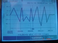
Here is what i have.
This is the VFA IPS.
Tested at clipping levels direct on dummy load.
First is the 20Hz test
Second the 20KHz
This is the VFA IPS.
Tested at clipping levels direct on dummy load.
First is the 20Hz test
Second the 20KHz
Attachments

Last edited:
I just ran some quick sine sweeps through the VHex+. No sign of DC offset even with hard clipping right up to 30kHZ. The highest offset voltage I saw was 10mV. It usually wanders around at less than 3mV. Nice balanced little amp!
- Home
- Amplifiers
- Solid State
- Revisiting some "old" ideas from 1970's - IPS, OPS