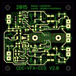
CDC-VFA-CCS V2.0 - measurements (standalone)
All measurements are performed with 20KOhm resistive load (sort of simulating the OPS).
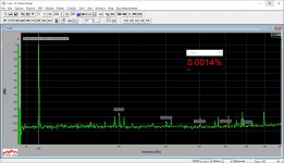
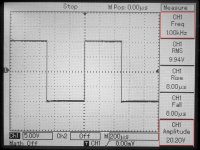
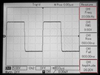
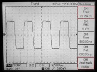
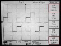
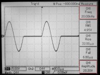
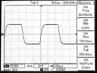
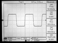
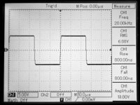
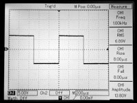
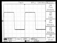
Most of the scope shots are done with 80V p-p output swing, although in the end there is a 20KHz / 100V one, as well as a "stairs" signal form just for fun.
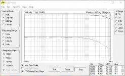
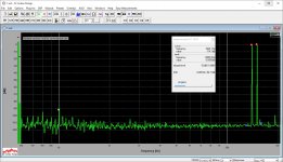
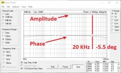
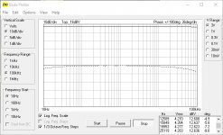
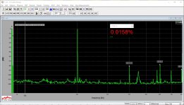
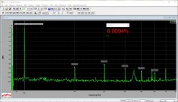
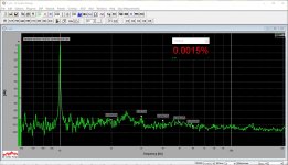
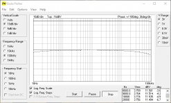
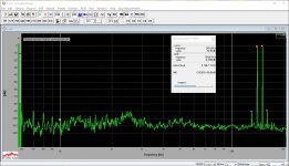
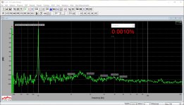
THD / IMD are very low (measured at 4.5V RMS sine wave), noise floor is mostly at around -110bd, slew rate is somewhat close to 60V / uS (this is a VFA after all). Good gain / phase responses.
Some tests with OPS connected will follow - need some preparation (cannot find the driver heatsinks for my IRFP-based Slewmonsters - they were removed for safety reasons).
BTW, I did not install the heatsink for the front-end now - tested as is, with VAS running pretty warm. Ordered the Wakefield ones, but it takes time for them to come.
All transistors except the input jFETs are hfe-matched within 30% tolerance.
Rails were at +/- 70V for these tests.
DC offset is very low and stable (well, no OPS, but still).
Cheers,
Valery
All measurements are performed with 20KOhm resistive load (sort of simulating the OPS).
Most of the scope shots are done with 80V p-p output swing, although in the end there is a 20KHz / 100V one, as well as a "stairs" signal form just for fun.
THD / IMD are very low (measured at 4.5V RMS sine wave), noise floor is mostly at around -110bd, slew rate is somewhat close to 60V / uS (this is a VFA after all). Good gain / phase responses.
Some tests with OPS connected will follow - need some preparation (cannot find the driver heatsinks for my IRFP-based Slewmonsters - they were removed for safety reasons).
BTW, I did not install the heatsink for the front-end now - tested as is, with VAS running pretty warm. Ordered the Wakefield ones, but it takes time for them to come.
All transistors except the input jFETs are hfe-matched within 30% tolerance.
Rails were at +/- 70V for these tests.
DC offset is very low and stable (well, no OPS, but still).
Cheers,
Valery
Attachments
-
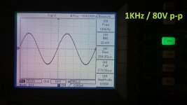 Image00001.jpg425.3 KB · Views: 1,608
 -
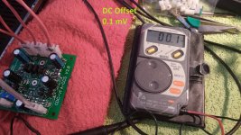 Image00010.jpg678.6 KB · Views: 304
 -
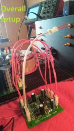 Image00009.jpg220.7 KB · Views: 322
 -
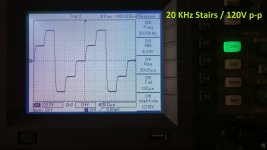 Image00008.jpg430.6 KB · Views: 220
 -
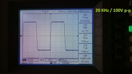 Image00007.jpg479.5 KB · Views: 207
 -
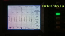 Image00006.jpg397.3 KB · Views: 206
 -
 Image00005.jpg433.9 KB · Views: 1,147
 -
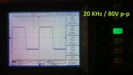 Image00004.jpg391.6 KB · Views: 1,216
 -
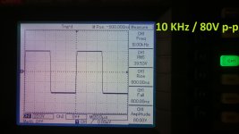 Image00003.jpg474.8 KB · Views: 1,295
 -
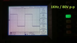 Image00002.jpg423.3 KB · Views: 1,430
It will be interesting to see how this works with BJT inputs. Not much to choose from in jfets on this side of the world.
BJT input version measurements
That was the plan 😉
Just replaced the input jFETs with good low-noise high-gain 2n5089 ones, matched with hfe = 940 😎 No other changes. BC550 will also work well here.
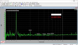
OK, noise floor is virtually at the same level. Distortion measurements are very slightly lower - well, we are talking about 0.0005% difference here. The result of slightly higher loop gain - about 4db. Can be compensated by slightly lower degeneration, but... who cares 🙂
Very low intermodulation in both versions.
Phase response is slightly better - 3.4 degrees @ 20KHz against 4.6 degrees for jFET version.
No difference in square wave response, slew rate, etc.
Offset was slightly adjusted to the same close-to-zero level.
I like this one as well 😎
Curious, if there will be some noticeable difference in the way they sound (unlikely). Although, I like jFETs at the input in general.
Cheers,
Valery
P.S. I will participate IBC2015 in Amsterdam, flying there tomorrow early morning, so my tests with OPS are going to happen after September 17 😉
It will be interesting to see how this works with BJT inputs. Not much to choose from in jfets on this side of the world.
That was the plan 😉
Just replaced the input jFETs with good low-noise high-gain 2n5089 ones, matched with hfe = 940 😎 No other changes. BC550 will also work well here.
OK, noise floor is virtually at the same level. Distortion measurements are very slightly lower - well, we are talking about 0.0005% difference here. The result of slightly higher loop gain - about 4db. Can be compensated by slightly lower degeneration, but... who cares 🙂
Very low intermodulation in both versions.
Phase response is slightly better - 3.4 degrees @ 20KHz against 4.6 degrees for jFET version.
No difference in square wave response, slew rate, etc.
Offset was slightly adjusted to the same close-to-zero level.
I like this one as well 😎
Curious, if there will be some noticeable difference in the way they sound (unlikely). Although, I like jFETs at the input in general.
Cheers,
Valery
P.S. I will participate IBC2015 in Amsterdam, flying there tomorrow early morning, so my tests with OPS are going to happen after September 17 😉
Attachments
-
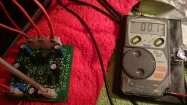 Image00020.jpg472.5 KB · Views: 216
 -
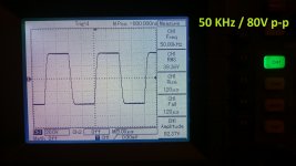 Image00007.jpg477.8 KB · Views: 177
 -
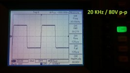 Image00005.jpg433.9 KB · Views: 176
 -
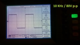 Image00002.jpg433.6 KB · Views: 170
 -
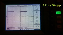 Image00001.jpg430 KB · Views: 219
 -
 12-bode-1mhz.JPG69.3 KB · Views: 244
 -
 11-imd-14-15khz.JPG199.5 KB · Views: 224
 -
 10-thd-020khz.JPG181 KB · Views: 222
 -
 10-thd-010khz.JPG184.3 KB · Views: 230
 -
 10-thd-001khz.JPG195.6 KB · Views: 298
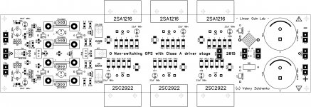
VERTICAL front-end + Non-Switching OPS with Class A driver stage
Finally... long time development.
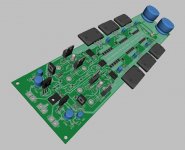
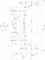
VERTICAL front-end is a combination of a number of my previous projects - it is based on CF-FET 2.0, plus the previous project's 2-nd stage (complementary differential + VAS) concept, utilizing a fully symmetric overall topology.
Non-switching OPS uses a bias clamping technology, similar to what Technics used in 80-90's integrated as well as power amps - the 2-nd spreader sets the bearing voltage for a diode clamp, maintaining the minimal current through the output devices when they are not in use. Simple, but rather efficient. Both, the 2-nd spreader and the diodes must be fast enough in order to avoid possible artifacts, in case their recovery is too slow.
Both components can be used in combination with the other IPS / OPS modules (VERTICAL was initially simulated with the Slewmaster OPS, for example). Both of them are designed with the highest possible open loop linearity in mind, having extremely low distortion with the loop gain being not too high. Both THD and IMD are going to be at the order of -100db, maintaining the high slew rate and virtually non-existing crossover distortion.
This OPS will also work perfectly with CDC-VFA-CCS V2.0, tested above.
NJW3281/1302 can be used instead of Sanken output devices (with lower maximum output power), as well as MJE15032/15033 can be used for the drivers. No PCB changes required.
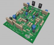
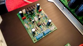
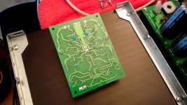
I will prototype the VERTICAL front-end first, then OPS will follow with live-testing. The prototype layout is fully TH. Terry, I did all my best to keep all the traces at the bottom side, but a few of them are still at the top - I can try to change them to the jumper wires, or would you like to try it as is?
Have fun 😉
Cheers,
Valery
P.S. Gerbers are available on request.
Finally... long time development.
VERTICAL front-end is a combination of a number of my previous projects - it is based on CF-FET 2.0, plus the previous project's 2-nd stage (complementary differential + VAS) concept, utilizing a fully symmetric overall topology.
Non-switching OPS uses a bias clamping technology, similar to what Technics used in 80-90's integrated as well as power amps - the 2-nd spreader sets the bearing voltage for a diode clamp, maintaining the minimal current through the output devices when they are not in use. Simple, but rather efficient. Both, the 2-nd spreader and the diodes must be fast enough in order to avoid possible artifacts, in case their recovery is too slow.
Both components can be used in combination with the other IPS / OPS modules (VERTICAL was initially simulated with the Slewmaster OPS, for example). Both of them are designed with the highest possible open loop linearity in mind, having extremely low distortion with the loop gain being not too high. Both THD and IMD are going to be at the order of -100db, maintaining the high slew rate and virtually non-existing crossover distortion.
This OPS will also work perfectly with CDC-VFA-CCS V2.0, tested above.
NJW3281/1302 can be used instead of Sanken output devices (with lower maximum output power), as well as MJE15032/15033 can be used for the drivers. No PCB changes required.
I will prototype the VERTICAL front-end first, then OPS will follow with live-testing. The prototype layout is fully TH. Terry, I did all my best to keep all the traces at the bottom side, but a few of them are still at the top - I can try to change them to the jumper wires, or would you like to try it as is?
Have fun 😉
Cheers,
Valery
P.S. Gerbers are available on request.
Attachments
-
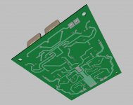
 102-PCB-2D.JPG138.3 KB · Views: 616
 -
 102-PCB-3D-01.JPG122.1 KB · Views: 405
 -
 102-PCB-3D-02.JPG69 KB · Views: 319
 -
 103-PCB-Silk.jpg955.4 KB · Views: 366
 -
 101-Sch.JPG676 KB · Views: 658
 -
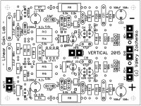 03-PCB-Silk.JPG648.5 KB · Views: 352
 -
 02-PCB-3D-02.JPG69.5 KB · Views: 321
 -
 02-PCB-3D-01.JPG109.4 KB · Views: 376
 -
 02-PCB-2D.JPG256 KB · Views: 729
 -
 01-Sch.jpg264.7 KB · Views: 724
Looks neat! I'll definitely want to build this one when things slow down a bit. What is the intended rail voltage?
Looks neat! I'll definitely want to build this one when things slow down a bit. What is the intended rail voltage?
At the moment it is setup for +/-70...75V DC, giving up to 250-280W of high-quality power accordingly. However it can be easily adapted for any rails from 40 to, say, 85. Just let me know what rails you'd like to use - I will give you the corrected values if required.
BTW, VERTICAL TH PCBs have arrived - I will start populating the prototype over the weekend.
Later on, after testing, I plan to make an SMD version of this front-end as well 😉
Attachments
CDC-VFA-CCS 2.0 - tested and measured with OPS
This one is tested with IRFP-based (5P) SlewMonster OPS module.
Version with BJT input devices (2N5089 x 2).
Very low noise, ultra-low distortion. Rather high slew rate for VFA.
Very good harmonics profile.
Excellent phase response.
Nice square and other complicated form waves response.
Listening test - later this week.
Cheers,
Valery
Attachments
-
 10-thd-001khz.JPG301.2 KB · Views: 402
 -
 10-thd-010khz.JPG277.6 KB · Views: 257
 -
 10-thd-020khz.JPG270.6 KB · Views: 254
 -
 11-imd-14-15khz.JPG301.8 KB · Views: 247
 -
 12-bode-100khz.JPG109 KB · Views: 272
 -
 DSC_1198.jpg718.8 KB · Views: 252
 -
 DSC_1199.jpg548.7 KB · Views: 210
 -
 DSC_1202.jpg684 KB · Views: 208
 -
 DSC_1205.jpg595.6 KB · Views: 220
 -
 DSC_1206.jpg642 KB · Views: 215
Final front-end configuration
Nothing has actually changed since my earlier standalone tests.
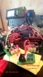
This is just to re-confirm the "as built" setup.
Tested with +/-50V DC shunt regulator in place.
Can be used with no regulator - right from +/-70V DC rails, but the noise gets higher for at least 6db, so I prefer regulated PSU for the front-end.
Sorry - no TH layout for this one 🙄
Cheers,
Valery
Nothing has actually changed since my earlier standalone tests.
This is just to re-confirm the "as built" setup.
Tested with +/-50V DC shunt regulator in place.
Can be used with no regulator - right from +/-70V DC rails, but the noise gets higher for at least 6db, so I prefer regulated PSU for the front-end.
Sorry - no TH layout for this one 🙄
Cheers,
Valery
Attachments
Hi vzaichenko,
off topic but was searching for a circuit diagram for a "Alto Macro 2400" and came across a thread of yours from 2010
http://www.diyaudio.com/forums/solid-state/248719-alto-macro-2400-amp.html
but the link is no longer active, and was wondering if you still have that diagram it would be very much appreciated, thanks
Dean
Hi vzaichenko,
off topic but was searching for a circuit diagram for a "Alto Macro 2400" and came across a thread of yours from 2010
http://www.diyaudio.com/forums/solid-state/248719-alto-macro-2400-amp.html
but the link is no longer active, and was wondering if you still have that diagram it would be very much appreciated, thanks
Dean
Hi, it's pretty easy to find just on the internet, for example - here:
>Alto Macro 2400 service manual<
Cheers,
Valery
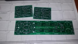
Some massive output boards and Vertical input boards arrived today.
Wow! Very cool )) You're a little bit ahead of me )) I didn't order the massive ones so far - populating the Vertical at the moment 😉
Meanwhile - VERTICAL front-end is tested!
Runs great 😎
😎
First of all - important addition - two 22pF caps for the VAS local stability improvement - C18, C19 - soldered on the back side of the board (sorry for that, they will be added to the final layout).
Slightly amended the lead comp caps - C13, C14 = 22pF, and small local shunt comp caps - C24, C25 = 10pF.
As expected - high speed, very low distortion, including low intermodulation, excellent square wave response even at 100KHz.
All live measurements are performed with IRFP-based Slewmaster OPS (5P).
TO-126 transistors (VAS) need a decent heatsink, especially if you run the board at +/-70V DC - or so - rails. I will try to reduce the VAS current a bit, the whole thing can also be tuned-up even further to have sharper square wave corners, but even the way it is it runs brilliantly, so I'm not sure we can win something here except measurement excellence 😉
Tested at +/-50V and +/-70V rails as is, without any changes - no difference in performance, although VAS obviously runs a bit hotter at higher voltage.
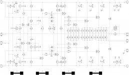
Pictures show:
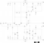
1) Schematic "as-is";
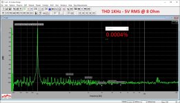
2) THD 1KHz;
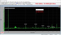
3) THD 10KHz;
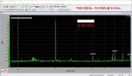
4) THD 20KHz;
5) IMD 14+15KHz;
6) Bode plot 10Hz - 100KHz;
7) Square wave 1KHz;
8) Square wave 20KHz;
9) Square wave 50KHz;
10) Square wave 100KHz.
Next step - high-performance "production" SMD layout with the ground plane.
Cheers,
Valery
Runs great
😎First of all - important addition - two 22pF caps for the VAS local stability improvement - C18, C19 - soldered on the back side of the board (sorry for that, they will be added to the final layout).
Slightly amended the lead comp caps - C13, C14 = 22pF, and small local shunt comp caps - C24, C25 = 10pF.
As expected - high speed, very low distortion, including low intermodulation, excellent square wave response even at 100KHz.
All live measurements are performed with IRFP-based Slewmaster OPS (5P).
TO-126 transistors (VAS) need a decent heatsink, especially if you run the board at +/-70V DC - or so - rails. I will try to reduce the VAS current a bit, the whole thing can also be tuned-up even further to have sharper square wave corners, but even the way it is it runs brilliantly, so I'm not sure we can win something here except measurement excellence 😉
Tested at +/-50V and +/-70V rails as is, without any changes - no difference in performance, although VAS obviously runs a bit hotter at higher voltage.
Pictures show:
1) Schematic "as-is";
2) THD 1KHz;
3) THD 10KHz;
4) THD 20KHz;
5) IMD 14+15KHz;
6) Bode plot 10Hz - 100KHz;
7) Square wave 1KHz;
8) Square wave 20KHz;
9) Square wave 50KHz;
10) Square wave 100KHz.
Next step - high-performance "production" SMD layout with the ground plane.
Cheers,
Valery
Attachments
-
 12-SQR-100KHz.JPG759.2 KB · Views: 224
 -
 12-SQR-050KHz.JPG705 KB · Views: 182
 -
 12-SQR-020KHz.JPG643.6 KB · Views: 181
 -
 12-SQR-001KHz.JPG668.1 KB · Views: 185
 -
 12-bode-100KHz.JPG68.4 KB · Views: 197
 -
 11-imd-14-15khz.JPG198.9 KB · Views: 208
 -
 10-thd-020khz.JPG180.9 KB · Views: 630
 -
 10-thd-010khz.JPG181.7 KB · Views: 644
 -
 10-thd-001khz.JPG194.4 KB · Views: 711
 -
 01-Sch.jpg273.2 KB · Views: 740
Slightly tuned-up
R19, R20 = 470
VAS runs cooler, performance is roughly the same (slightly lower distortion 😉)
OPS is re-biased to match the lower VAS quiescent current.
R19, R20 = 470
VAS runs cooler, performance is roughly the same (slightly lower distortion 😉)
OPS is re-biased to match the lower VAS quiescent current.
Attachments
-
 22-bode-100KHz.JPG68.9 KB · Views: 181
 -
 21-imd-14-15khz.JPG197.4 KB · Views: 182
 -
 20-thd-020khz.JPG180.8 KB · Views: 188
 -
 20-thd-010khz.JPG181.4 KB · Views: 186
 -
 20-thd-001khz.JPG193.5 KB · Views: 306
 -
 19-Sch.jpg273.2 KB · Views: 331
 -
 DSC_0075.jpg409.2 KB · Views: 164
 -
 DSC_0076.JPG388.2 KB · Views: 173
 -
 DSC_0078.JPG772.1 KB · Views: 273
 -
 DSC_0079.JPG748.5 KB · Views: 270
reducing R19/20 increases the quiescent current through the Qs.
That usually gets the transistor further up the fT curve, i.e. faster.
It's a common tweak I often do.
There are few, if any transistors, that are fast with only 1mA of current. Many need at least 10mA and only a few perform quickly with 2mA.
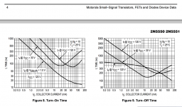
Unfortunately neither ONsemi, nor Fairchild, show us an fT curve for the 2n5551.
Can we infer anything about fT, from the turn on turn off plots?
That usually gets the transistor further up the fT curve, i.e. faster.
It's a common tweak I often do.
There are few, if any transistors, that are fast with only 1mA of current. Many need at least 10mA and only a few perform quickly with 2mA.
Unfortunately neither ONsemi, nor Fairchild, show us an fT curve for the 2n5551.
Can we infer anything about fT, from the turn on turn off plots?
Last edited:
reducing R19/20 increases the quiescent current through the Qs.
That usually gets the transistor further up the fT curve, i.e. faster.
It's a common tweak I often do.
There are few, if any transistors, that are fast with only 1mA of current. Many need at least 10mA and only a few perform quickly with 2mA.
Unfortunately neither ONsemi, nor Fairchild, show us an fT curve for the 2n5551.
Can we infer anything about fT, from the turn on turn off plots?
Well, indirectly turn on/off plots are showing that within the reasonable range of collector currents (up to 10-20 mA) it is exactly as you say - the higher Ic, the higher the speed (and thus the fT).
But we have to keep in mind overall SOA - at roughly 40-50V Vce it's difficult to go above 5mA Ic (too hot).
I'm running those 5551/5401 vertical differential cascades at around 2.5mA, VAS at 10-15mA - the topology is fast enough by itself (and pretty linear as well) 😎
Attachments
Your change and the changed results seem to confirm that the transistor is responding to an increased fT.
As I see it you balance the compromises.
Change to a cascode, or change to a To126, or run it hotter, or leave as is.
As I see it you balance the compromises.
Change to a cascode, or change to a To126, or run it hotter, or leave as is.
Hi Guys,
Jeff sent me some boards. The Vertical and the big OPS. I have just a couple questions. First is about the OPS. What if any advantage does have over the Slewmaster OPS? I have never used the Sankens. Do the get treated differently than say the MJL4381/4302? What id the ideal rail voltage to take advantage of them?
For the Vertical, can I use the schematic from post #155?
Thanks, Terry
The big Sankens are like 2 MJLs. They aren't quite as well matched as the ON devices, but they are much tougher to hurt and cool much better. Valery has this tuned for 75V. Newark always has 2SA1295/2SC3264 on sale if you want to use big Sankens.
I haven't had a chance to build the output boards yet, so I can't tell you much about their operation.
I think the schematic in post 155 is the preferred schematic. Did you see the note to add an extra pair of caps to the back of the input boards? Post 154.
I haven't had a chance to build the output boards yet, so I can't tell you much about their operation.
I think the schematic in post 155 is the preferred schematic. Did you see the note to add an extra pair of caps to the back of the input boards? Post 154.
- Home
- Amplifiers
- Solid State
- Revisiting some "old" ideas from 1970's - IPS, OPS