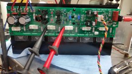
This build's being a bit of a challenge in the supply area, but I've managed to get one channel up and running on 42V rails. Excellent results so far. Now I need to get a second channel running and give it a listen!😀
Excellent.Great looking one!
This one will handle 1ohm if required 😉

Jef, this is a very professional job. I like your modular system very much.
If this can handle 1R load this will be a reference amplifier,
Congratulations for you and Valery!


Are these the modular input stages? What does the modular output stage look like?
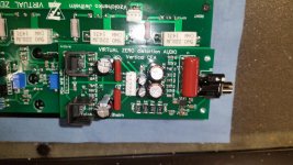
Hi X, post #793 - right picture, top board is the modular NS-OPS with no IPS board installed.
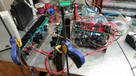
I'm running a mono channel with the Vertical VFA input right now without nested feedback. All these are silent. No turn on or turn off pops. Dead silent with open inputs. Sounding great! CFA is still my favorite though. I'm scrambling to get some orders ready to ship, so I can't get a second channel fired up.
This is our most advanced "system" amplifier series, utilizing lots of cool "old" ideas in their new incarnation, and I'm really happy the new boards, designed by Jeff, work as expected. Great, great job Jeff!
DiagoHex+
Hello All,
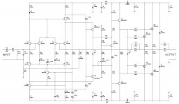
Following certain success of VHex amplifier, inspired by Albert (abetir) and published in his thread >HERE<, also inspired by Paul's (mcd99) idea of additive current drive (contrary to subtractive in VHex), here is the version of the amp with more advanced, more symmetric current-drive front-end. OPS is exactly the same.
I have named it DiagoHex+.
Distortion level is lower a few times, output power is roughly the same at the same rails voltage (up to 150W @ 8 ohm with +/-60V dc).
If somebody would like to make a DIY-friendly single-layer layout - more than welcome. For Q7, Q21, Q22 local snap-on heatsinks are recommended.
Some other rail voltages are possible - just let me know, I will give you some corrected resistors' values.
Cheers,
Valery
Hello All,
Following certain success of VHex amplifier, inspired by Albert (abetir) and published in his thread >HERE<, also inspired by Paul's (mcd99) idea of additive current drive (contrary to subtractive in VHex), here is the version of the amp with more advanced, more symmetric current-drive front-end. OPS is exactly the same.
I have named it DiagoHex+.
Distortion level is lower a few times, output power is roughly the same at the same rails voltage (up to 150W @ 8 ohm with +/-60V dc).
If somebody would like to make a DIY-friendly single-layer layout - more than welcome. For Q7, Q21, Q22 local snap-on heatsinks are recommended.
Some other rail voltages are possible - just let me know, I will give you some corrected resistors' values.
Cheers,
Valery
Attachments


OK - this is a compact BJT OPS, something we were missing. IPS modules are fully compatible with the bigger NS Modular OPS "carrier" boards.
That looks really nice! Swappable IPS is cool - will let one do some quick testing without investment in entire board with OPS.
Babies looks good!🙂The modular version of the diagonal input and the new Mini Modular Output boards are almost ready for a test run.
A separate input stage is a great idea for serviceability and testing, but I've always thought the design takes up too much chassis space, and the input always seemed to end up too close to the power supplies for my liking. With the switch to SMT and being able to shrink it enough to stack the boards seemed to have solved those issues.
We've switched to separate regulated supplies for the input stages. so there's no more hot power resistors and zeners on the inputs. The actual cost difference between the resistor, zener combination to actual regulators is minimal.
I need to get these new designs into chassis and properly tested, but so far they are easier and faster to assemble and test. I've also designed both of them to be adjusted without needing to disassemble the amplifier. All adjustment pots are accessible from the top of the amplifier, and emitter resistors are accessible from the protection circuit connectors, so no more inserting probes near high current devices.
Last edited:
Babies looks good!🙂
I'm looking forward to seeing your results from it's big brother builds. You should be seeing them soon.
Do i expect something?🙂I'm looking forward to seeing your results from it's big brother builds. You should be seeing them soon.
I sent about 10lbs of boards and parts your way a week ago. They should be there soon.
Waiting the pack

A new amplifier is on the road

I sent about 10lbs of boards and parts your way a week ago. They should be there soon.
How much for a pair of Diagohex+ IPS and vFET OPS daughter/mother boards? I guess I should PM/email you since that would be commercial...
10lbs - is there like a 300va trafo in there?
These are still in the testing phase so nothing is definite, input boards are $24.90/pr. Output boards will be $34.90/pair and a set of supply boards will be $38.90 (2 each main supplies and regulator boards). The control/protection board to start the amp and supplies is $14.90. Other supply/ control options can be done. These are what I'm testing with right now.
Attachments
- Home
- Amplifiers
- Solid State
- Revisiting some "old" ideas from 1970's - IPS, OPS