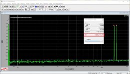
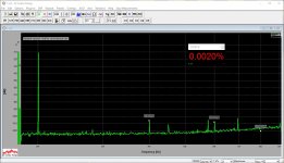
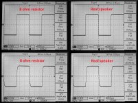
Here are the same measurements for 5W @ 8 ohm.
It definitely goes easier with the resistor - no surprise 😛 - but still looks pretty cool with the speaker.
I will also try to see the square wave on the speaker later today 😉
It definitely goes easier with the resistor - no surprise 😛 - but still looks pretty cool with the speaker.
I will also try to see the square wave on the speaker later today 😉
Attachments
-
 21-@00.JPG66.7 KB · Views: 536
 -
 32-@Tube-IMD-14-15k-6.5v.JPG277.9 KB · Views: 172
 -
 31-@Tube-THD-20k-6.5v.JPG175.4 KB · Views: 164
 -
 31-@Tube-THD-10k-6.5v.JPG174.6 KB · Views: 162
 -
 31-@Tube-THD-01k-6.5v.JPG183.4 KB · Views: 155
 -
 31-@00.JPG65.1 KB · Views: 152
 -
 22-@Tube-IMD-14-15k-6.5v.JPG277.4 KB · Views: 477
 -
 21-@Tube-THD-20k-6.5v.JPG174.8 KB · Views: 490
 -
 21-@Tube-THD-10k-6.5v.JPG174.8 KB · Views: 505
 -
 21-@Tube-THD-01k-6.5v.JPG184 KB · Views: 521
real good!
practically the only IMD showed significant differences...
but distortions still damn low!
great!
practically the only IMD showed significant differences...
but distortions still damn low!
great!

Almost no one posts scope pics into speaker loads, or simulated speaker loading.
That makes comparison with other builds nearly impossible.
Do you think your "real load" results are good, or excellent, compared to other designs?
Could you post a sch of a simulated speaker load so that others can try a similar test if they care to compare when loading is reactive.
That makes comparison with other builds nearly impossible.
Do you think your "real load" results are good, or excellent, compared to other designs?
Could you post a sch of a simulated speaker load so that others can try a similar test if they care to compare when loading is reactive.
Almost no one posts scope pics into speaker loads, or simulated speaker loading.
That makes comparison with other builds nearly impossible.
Do you think your "real load" results are good, or excellent, compared to other designs?
Could you post a sch of a simulated speaker load so that others can try a similar test if they care to compare when loading is reactive.
These ones are physically measured on the real Monitor Audio RS-8 - I had to cover it with a few winter coats, so that 1KHz does not drive me crazy too much 😀
Although, Richard Marsh has sent me a good speaker model the other day - useful for simulations. I'll try to find it must be somewhere in my simulation archives.
Cheers,
Valery
I think ESP has suggested a sim model for a full range speaker and for a 2way speaker.
There are others on the internet.
Just pick one and ask that the Members to adopt it so that comparisons can be made.
Maybe a new Thread for this real test procedure?
There are others on the internet.
Just pick one and ask that the Members to adopt it so that comparisons can be made.
Maybe a new Thread for this real test procedure?
Hi Pawel,
Thanks for reminding me 😀
Here are THD and IMD measurements for 2W @ 8 ohm.

These ones are physically measured on the real Monitor Audio RS-8 - I had to cover it with a few winter coats, so that 1KHz does not drive me crazy too much 😀...
my later thought:
probably this test was useless to show real life differences resistor vs speaker:
because the speakers membranes were accoustically isolated
and there was no microphonic effects on them.
Better test will be with the wool in the ears
not the clothes on the cones😀
my later thought:
probably this test was useless to show real life differences resistor vs speaker:
because the speakers membranes were accoustically isolated
and there was no microphonic effects on them.
Better test will be with the wool in the ears
not the clothes on the cones😀
Ah, I have tried to remove the covers for some time - no difference.
And it was still pretty loud. So - no problem.
The electrical equivalent of a speaker which is an electric linear motor with load ( air mass)
is easy to derive ( see Beranek for example) but is not just a challenging load for any amp.
The speaker above its resonant frequency is predominantly inductive, below capacitive.
The hard reality test is with multi-way speakers and "crazy" crossovers, which may provide very low real loads ( 2 ohms for ex.) with high phase shifts. Here many amps fail miserably which are excellently performing with either real loads or real speakers.
Consequently , amps for active speakers are much simpler and the overall results are yet better as for amps driving multiway speaker with crossover, as the total system thd is mainly dominated by the speaker. For active speakers, amps with non switching behavior should indeed give even better results. Because at output below say 200 milli watts distortion is dominated by the amp.
Another test is backward. The speaker model has a current source which feeds through the elements of the electrical speaker model current into the amp's output , its input shorted. This simulates very well sharp short impulses of real music, where the motion of the speaker's membrane continues - mechanical inertia - and induces a voltage in the driver coil. The amp is supposed to short this voltage but these tests unveil the amps output is very far from a real resistor with a value almost zero.
This test tests basically the negative feedback. With the somewhat disappointing results
( keyword : fine dynamics reproduction) engineers started to design amps without global feedback.
Ah, I have tried to remove the covers for some time - no difference.
And it was still pretty loud. So - no problem.
Amp needed name.😀
re reviving old ideas...
one of these was nested feedback loops. The output stage had only local feedback - for ex. emitter degeneration, and no feedback loop stretched over more than 2 stages of the amp.
Obviously in mass production that required too much of test and adjusting thus the method came only in a few but high priced commercial amps with relatively small power, 70 watts or so.
re reviving old ideas...
one of these was nested feedback loops. The output stage had only local feedback - for ex. emitter degeneration, and no feedback loop stretched over more than 2 stages of the amp.
Obviously in mass production that required too much of test and adjusting thus the method came only in a few but high priced commercial amps with relatively small power, 70 watts or so.
Yes, designs with no global loop is an interesting area, but normally require a lot of tuning and very much depend on particular build quality 🙄
Interesting... I had to increase C9, C10 pre-drivers shunt caps up to 150pF each in order to eliminate small artifacts, visible on the spectrums close to the central frequency, like here (now they are gone):
http://www.diyaudio.com/forums/solid-state/248689-xhs-xtra-high-speed-design-5.html#post4557827
Tested the new OPS with both VERTICAL and CDC-VFA-CCS V2 - excellent performance.
I will show the measurements tomorrow. Also interesting - with this OPS, THD dependency on frequency is rather low - CDC VFA shows (50W):
01 KHz - 0.0084%
10 KHz - 0.0085%
20 KHz - 0.0090%
I like it more and more 😉
Although, my favorite combination is still with TubSuMo IPS - the one having a tube at the input.
Have you listened to this yet, or are you still just testing? I'm curious how the sound compares to the TubSomo output board.
I have listened to the configuration TubSuMo IPS + non-switching OPS. Sounds very detailed, with airy, natural highs and elastic, punchy bass. Nice.
To compare with TubSuMo lateral FET OPS, I need to arrange a true A/B test - otherwise it will be too subjective, difficult to compare.
To compare with TubSuMo lateral FET OPS, I need to arrange a true A/B test - otherwise it will be too subjective, difficult to compare.
I found TubSomo to have not as detailed highs compared to other amps. I've wanted to experiment more with it, but haven't had time. I'm looking forward to having some time to try this one!
I found TubSomo to have not as detailed highs compared to other amps. I've wanted to experiment more with it, but haven't had time. I'm looking forward to having some time to try this one!
That's strange. I found the Tubsumo to be very detailed. The IGI2 that I built is more subdued.
This is what's got me wanting to experiment more. I'd like to figure out why mine isn't as crisp. I had quite a battle to get a running pair when I first assembled TubSomo. I ended up junking the first pair because of odd DC offset that I never found a cause for.
Last edited:
- Home
- Amplifiers
- Solid State
- Revisiting some "old" ideas from 1970's - IPS, OPS