I found a few older threads here mostly regarding older parts, and some stability solutions which do not yield good results with parts now available. So I figured we could have a thread dedicated to using the Exicon mosfets in novel ways I have not seen mentioned here.
Like most people, I encountered oscillation when using multiple devices, and tried the usual higher gate resistor values, and capacitors. By the time these measures could help, the amp was too slow, which in turn caused feedback loop stability issues. So, I did some research and found that that the culprit is loop currents between case and source leads with multiple devices. When TO-3 devices are mounted to a live heat sink, and source lead trace goes right to one of the case screws like the Soundcraftsmen PCR800, it's all good.
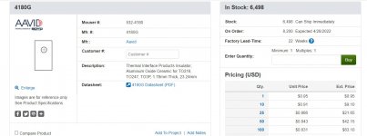
But that doesn't happen with the plastic case devices. They usually don't make a good connection with the heat sink at all, but instead form a good capacitor - perfect Colpitts oscillator ! And if you used mica insulators, it's real bad. Here is the solution : isolate the devices from heat sink with aluminum oxide pads such as ones from Aavid, found at most major parts vendors. I then used 330R gate resistor and 47pf right from gate to drain on N channel device, and 220R gate resistor, and 100 pf cap for P channel device. Easily obtained 80 v/us speed with stability. Even works well dual differential front ends. For the double die devices , I found that 220R gate resistor and 68 pf across gate and drain for N channel, and 150R , 150 pf for P channel worked well. These parts must be on each device, with capacitors right at gate / drain leads.
Now here is the good part, it turns out that lateral MOSFETs make great driver stages. Way faster than using large power transistors, and far better than building up triple Darlingtons.
Any good VAS stage will drive one pair of the single die Exicons very well. The sound is fantastic. MOSFETs break the path of current draw being passed all the way back to input stage as happens with pure bipolar design. If anyone is interested in this subject, I would be happy to share more info, and schematics as well.
Like most people, I encountered oscillation when using multiple devices, and tried the usual higher gate resistor values, and capacitors. By the time these measures could help, the amp was too slow, which in turn caused feedback loop stability issues. So, I did some research and found that that the culprit is loop currents between case and source leads with multiple devices. When TO-3 devices are mounted to a live heat sink, and source lead trace goes right to one of the case screws like the Soundcraftsmen PCR800, it's all good.
But that doesn't happen with the plastic case devices. They usually don't make a good connection with the heat sink at all, but instead form a good capacitor - perfect Colpitts oscillator ! And if you used mica insulators, it's real bad. Here is the solution : isolate the devices from heat sink with aluminum oxide pads such as ones from Aavid, found at most major parts vendors. I then used 330R gate resistor and 47pf right from gate to drain on N channel device, and 220R gate resistor, and 100 pf cap for P channel device. Easily obtained 80 v/us speed with stability. Even works well dual differential front ends. For the double die devices , I found that 220R gate resistor and 68 pf across gate and drain for N channel, and 150R , 150 pf for P channel worked well. These parts must be on each device, with capacitors right at gate / drain leads.
Now here is the good part, it turns out that lateral MOSFETs make great driver stages. Way faster than using large power transistors, and far better than building up triple Darlingtons.
Any good VAS stage will drive one pair of the single die Exicons very well. The sound is fantastic. MOSFETs break the path of current draw being passed all the way back to input stage as happens with pure bipolar design. If anyone is interested in this subject, I would be happy to share more info, and schematics as well.

Please !If anyone is interested in this subject, I would be happy to share more info, and schematics as well.
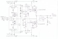
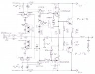
I attached the schemo as tested with double die devices. I did change R55 to 560R, and R56 to 220R for better bias trimmer range. I have Q28 near heat sink but not attached, this compensates for ambient temp nicely. The circuit is good for over 150 w into 4 ohms, more with an extra stout power supply. I tested the same circuit with two sets of output devices and +/- 75v , and was good for 375w. I often do schemos of in this cut and paste style with something just tested , and do a better one latter . Also attached is the insulator I spoke of at Mouser, and many vendors sell it.
I will do a quick schemo for the single die MOSFET driver , bipolar output version soon.
I have designed amplifiers for 30 years, mainly contract manufactured and private labeled for installers in the studio, lounge, and club markets, I'll post about that in the solid state forum here. But there is a lot to share now that I'm semi-retired.
For those mentioning vertical MOSFETs , I have experience with them as well, and plan to start a dedicated thread on dealing with the higher Vgs threshold for good results and rail to rail swing.
Attachments
I believe Rendardson Audio has some great lateral FET recommendations, both for schematics and parts. He was giving some unbelieveably low figures for distortion 🙂
Without simulating your circuit, there is already a possible problem in RC filter/delay driving the output transistors, then there is an RC circuit equivalent in the transistors themselves, and then you have LC output into a reactive load... this can't end well!
I spent days in simulating and trying to understand the output filter, please do this as well, and use a "non-inductive" (but that's a relative term 😉 ) resistor in parallel with the output inductor.
How does that work: the inductor absorbs an output spike and the resistor across it dissipates it into heat. So.. a correct combination needs to be fine-tuned. You can do it with any simulated voltage output in LTSpice, but do it. You can't just take some random values and expect them to work. What used to work with 8-ohm speakers may not work with 2-ohm speakers.
and... always use high frequency routing techniques and such. especially for emitter/drain. u= L* dI/dT
There are seversl type of ferrite, with very different frequencies where they become lossy, which is what you want to kill oscillationAnd always use ferrites directly on the gate leads!
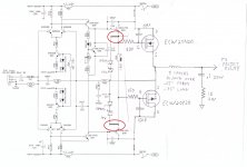
i see 4 sets of compensation.
i use a very similar circuit but with only 1 compensation, in a place where the posted circuit has none, across the vas.
i use a very similar circuit but with only 1 compensation, in a place where the posted circuit has none, across the vas.
My circuit is just based on the very well proven Soundcraftsmen PCR800. I just changed the front end to dual differential to even up the rise and fall slew rates. A number of compensation methods will work, however ; as per the premise of this thread the Exicon MOSFETs in the plastic case need special steps when using multiple devices. The shown circuit has been built. It will pass 70khz square wave to clipping, just disconnect output zobel if trying that. It is stable without it. The coil could be bypassed with a resistor, but that would reduce the value against blocking RF picked by speaker wires. I connect test gear before the coil to look at square waves, and slew rate tests. It has no effect on audio. The PCR800 schemo includes the clip indicator, it's not part of the audio chain.
Attachments
In the old days I did similar driver tests and found the hitachi LatFETs 2SK213/2SJ79 being superior to bjt drivers. I used one pair of these to drive 36 pairs of Hitache TO-3 laterals in a 5kW Monoblock. Sadly these latFETs disappeared from the market for a long time.
I buy my Exicon laterals from Profusion. About the only place left who sources them. They seem to have plenty but not cheap.In the old days I did similar driver tests and found the hitachi LatFETs 2SK213/2SJ79 being superior to bjt drivers. I used one pair of these to drive 36 pairs of Hitache TO-3 laterals in a 5kW Monoblock. Sadly these latFETs disappeared from the market for a long time.
like everybody here does. But how does this relate to my posting? Exicon never offered latFETs for driver applications like the ones I mentioned.I buy my Exicon laterals from Profusion. About the only place left who sources them. They seem to have plenty but not cheap.
As far as I remember this is what I wrote before. Why do you echo me?"Sadly these latFETs disappeared from the market for a long time."
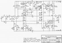
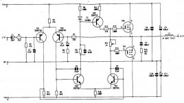
Here is the schemo of the Exicon single die MOSFETS used as drivers in actual test circuit. The output network is the same as before, One output pair is shown to keep schemo simple . I tested this up to 4 output pairs.
Details :
1 pair as shown +/- 55v 150w 4 ohms ,
2 pairs (22R base shunt resistors changed to 15R) +/- 65 v 250w 4 ohms ,
3 pairs (22R base shunt resistors changed to 10R) +/- 75v 400w 4 ohms ,
1 additional pair onto the 3 pair circuit , 600w 2 ohms.
The bias Vbe transistor must be mounted to heatsink. I set the bias for 10 ma per device, some people prefer more, ok as long the heat is under control.
The MJL21195 , 96 are wide SOA devices , if you use 2SA1943, 2SC5200 you would need twice as many with 0.47R 5w emitter resistors in each case.
I will compare bipolar output devices in its own thread. I will also post about HEXFETS as well.
Being that this thread is about the Exicon MOSFETS, I did not address a lot of circuit build details, but if there is interest, I can post build and design details in the correct forum relating to any of the parts I post about here.
Attachments
- Home
- Design & Build
- Parts
- Revisiting lateral MOSFET stability