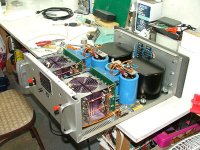
I really have to mention that this KMA-160 sample is riddled with manufacturing defects. I just noticed a solder bridge in the Darlington pair that drives the negative power rail. That's on top of the blatant rework on the diff amp and the ridiculous capacitors on the wrong side of the board.
Krell quality?
Krell quality?
Speaking of KMA-160...
I'm curious, how did they accomplish the 160?
One driver board, two sides of ouputs?
Two driver boards, paralleled outputs?
Two driver boards, bridged outputs??
And, why not bridged, if they didn't?
_-_-bear
I'm curious, how did they accomplish the 160?
One driver board, two sides of ouputs?
Two driver boards, paralleled outputs?
Two driver boards, bridged outputs??
And, why not bridged, if they didn't?
_-_-bear
Hello jmb;
read your thread with great interest. Maybe interesting for you that I am currently working on a similar project. I got a faulty KSA-100 EUR for a very (very,very...) small fee. According to Steven Leckrone, this KSA-100 EUR was called KSA-80B when being sold in the U.S.
The driver board which is located in my amp looks very, very similar to yours shown on the picture (fortunately without parts being burnt that much...). Of course my amp does not have symmetrical inputs - only RCA`s.
Due to other important projects (well--- I do have another Krell Power amp here for repair, it is a KSA-100S with sustained plateau biasing... much more complicated circuit 🙁) I did not get very far now with my KSA-100 EUR, but: Both channels are faulty on my amp (of course as I already told my amp wasn`t on fire as was yours...); all output devices are OK; I have strong DC offset @ both outputs; suspecting a fault in the +/- 80 and +/- 40 Volt regulators on the driver boards.
Well maybe we could exchange some information during our project, and both participate from each other`s knowledge. If there are any totally burnt parts on your pcb`s, I can tell you value/types of these.
Please do not hesitate to contact me via pm, if I can do something for you.
cheers, audiomatic
Here's my new layout for the input board. It's a 600KB PDF:
Layout
I kept the basic concept of the original layout, but changed a few things. Most obviously, I added the coupling capacitors, and they take up a lot of room on the left. I also changed the input wiring from soldered to a Molex Micro-Fit connector. On the 38V regulators (Q104, Q105) I added substantial heatsinking. On Q25 and Q26 I added heatsinks where before there were none. On the buffer stage (Q201-204) I think my layout makes a lot more sense than the original, and it's also much more compact. I try to keep a consistent distance between the balanced traces driving these gates, whereas Krell let them wander apart somewhat.
All the footprints and pinouts are the same as the original, save for the added heatsinks. If you used regular Yageo or BC 1/4W metal film resistors instead of Dale, you'd save a ton of space. But as we're constrained by the hole pattern here, there's not much sense in doing that.
The only modification I'm thinking of making is to bias two of the current sources with LEDs instead of resistors. I don't think that's really going to take up terribly much room.
Hi jwb,
I've always had better luck and performance using LED's as current source references. There was a great series of posts regarding noise levels among different LED's. All in all, the performance is so improved that the noise levels aren't that important.
It sounds like your Krell is getting a performance kick.
-Chris
I'm not expecting a big improvement, but LED references are my standard operating procedure for current sources.
Maybe I'll get a bit of a boost in CMRR.
Maybe I'll get a bit of a boost in CMRR.
More stable operation and much quieter background. I love it when background noise drops away.
I've noticed this about you from previous posts. They also work very well in power supply regulators.
I've noticed this about you from previous posts. They also work very well in power supply regulators.
Which parts in this design are important to match? I assume the input FETs need to be matched for Idss, and the diff amps need to be matched for Vbe, as well as the resistors in the diff amps. What about Vgs matching for the FETs in the middle stage? Any other parts I'm neglecting?
Nevermind the outputs and the drivers, since I'm using the original parts there.
Nevermind the outputs and the drivers, since I'm using the original parts there.
How about a two-transistor feedback-type current source? Much higher output impedance, and not terribly complicated, either.
Rod Elliot gives it a quick discussion here:
http://sound.westhost.com/ism.htm#real-life
regards, jonathan carr
Rod Elliot gives it a quick discussion here:
http://sound.westhost.com/ism.htm#real-life
regards, jonathan carr
I have fiddled with a LED biased current source with a cascode and the cascode improved the performance of the current source a lot, sim wise that is. I actually added a second cascode as well just for fun but then the performance was more determined by the voltage reference noise rather than the transistors themselves.
Has anybody tried cascoding a LED referenced current source in real life, it should help if you consider dynamic thermal stability for the current as well.
Has anybody tried cascoding a LED referenced current source in real life, it should help if you consider dynamic thermal stability for the current as well.
Yes I have used cascoded, LED-referenced current sources in voltage regulators before. The impedance is absurd (high tens of megaohms).
Additional Krell schematics and photos
I have posted a new thread on some of the older Krell designs including the KSA-50 and KSA-100. There are schematics and photos. Here is the link to the page:
http://home.ca.inter.net/~lloyd.maclean/Krell/Krell.htm
here is one of the photos:
I have posted a new thread on some of the older Krell designs including the KSA-50 and KSA-100. There are schematics and photos. Here is the link to the page:
http://home.ca.inter.net/~lloyd.maclean/Krell/Krell.htm
here is one of the photos:
Attachments
Great info, sir. D5 and D6 in your amp has been replaced with resistors in my amp. Do you have any idea why they might have done so? I was considering going back to 2-terminal current sources as part of my modifications.
The two current sources on the differentials are operating way in excess of their rated power. They idle with 16Vc-e and are programmed for 22mA, or more than 350mW. The max power is 300mW at 20C ambient, which of course is not the ambient temperature inside an amplifier.
Certainly a more manly current source is required here. The C2240 is OK for the amp and the cascode but not for the current source.
ZTX450 seems to have the required SOA.
Certainly a more manly current source is required here. The C2240 is OK for the amp and the cascode but not for the current source.
ZTX450 seems to have the required SOA.
I'm not sure why they switched. There was quite a bit of variation from unit to unit on some older models.
I wonder why they use so much current in the differential (20mA total). With ±39V rails this causes a real power dissipation headache. Doesn't 2mA seem far more reasonable, with all the resistors increased 10x? Does the 20mA current have some kind of natural advantage in terms of noise?
2 mA does make more sense, but I think they were going for speed. Still, 20 mA seems a bit high.
-Chris
-Chris
I seem to recall that LEDs as current source references etc, were found to not be a good idea because they happen to modulate with a pulsating light source shining upon them! As with a fluorescent light... 
Of the many ways of making a good current source, I think I'd pick some others first, including some of the purpose built references that are cheap and come in the form of a small transistor package...
_-_-bear
Of the many ways of making a good current source, I think I'd pick some others first, including some of the purpose built references that are cheap and come in the form of a small transistor package...
_-_-bear
In this case I'm going to use LM329 buried zener, but only because I want 6V and don't want to stack up 4 LEDs. If you worry about the photovoltaic effect of LEDs (and if you were, you'd also be worried about light-coupled crosstalk within your circuit), just put a blob of opaque gunk over them.
- Home
- Amplifiers
- Solid State
- Reverse engineering Krell KMA 160